Potentiometer Motor Control Breadboard
Run MicroSim in Fullscreen Edit in the p5.js Editor
About This MicroSim
Turn a three-terminal potentiometer to change the base drive of a 2N2222 NPN transistor. The transistor controls a small DC motor on the breadboard. A 1N4001 flyback diode connects across the motor, with its silver cathode band toward the positive supply.
The motor uses analog voltage control. As the knob rises, the transistor moves from cutoff through its active region to saturation. Motor speed does not rise in direct proportion to knob position. The readouts show estimated base current, motor current, motor voltage, speed, collector voltage, and transistor power.
How to Use
- Move Pot position between 0% and 100%. The readouts update even while paused.
- Press Start to animate conventional current and motor rotation. Pause freezes the animation, scope history, and flyback time.
- With the motor running, lower Pot position directly to 0%. This removes base drive while keeping the motor supply connected.
- Watch the brief flyback current through D1. The electrical transient is displayed 1000 times slower so you can inspect it. Lower the pot to 0% while paused to freeze its initial state, then press Start.
- Select Show scope in a fullscreen window at least 900 pixels wide. The red axis is motor current in mA; the blue axis is collector voltage in volts. The horizontal axis shows successive samples, not a calibrated time axis.
- Raise the potentiometer to restore drive. Reset restores 45%, clears history, and pauses.
The motor illustration and lead spreading are diagrammatic. Use the labeled electrical terminals and the wiring table; a real 2N2222-family part's lead order depends on its manufacturer and package.
Lesson Plan
Audience: Beginning electronics students, grades 9–12 and adult beginners.
Duration: 20–25 minutes.
Prerequisites: Breadboard connectivity, voltage dividers, Ohm's law, diode polarity, and NPN base/collector/emitter terminals.
Learning Objective
Apply: Students will demonstrate control of a motor by adjusting potentiometer position, record the resulting base drive and motor response, and trace the diode's protective current path when base drive is interrupted.
Circuit and Components
The potentiometer connects across the supply. Its wiper feeds a fixed 1 kΩ resistor into the base. The resistor limits base current even at the top end of the knob. Q1's emitter connects to ground; its collector connects to the motor's negative terminal. Motor current comes through Q1 from the supply, rather than through the potentiometer.
Diagram: Potentiometer-Controlled Motor with Flyback Protection
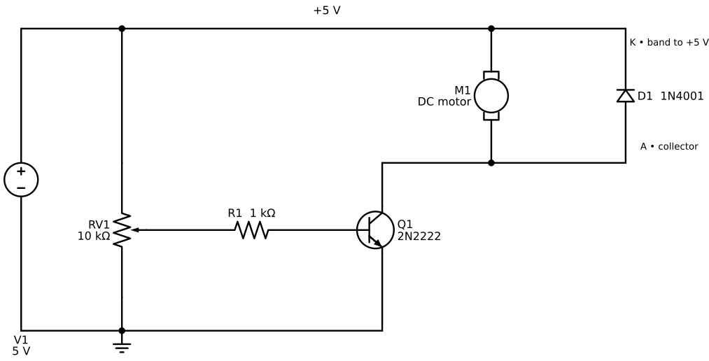
Download schematic SVG · Schemdraw Python source
| Part | Value or role | Breadboard terminals |
|---|---|---|
| Supply | 5 V DC | Positive T+1; negative B−1 |
| RV1 | 10 kΩ potentiometer | High d2; wiper e4; low e6 |
| R1 | 1 kΩ base resistor | j8 to j11 |
| Q1 | 2N2222 NPN | Collector h10; base h11; emitter h12 |
| M1 | Illustrative small DC motor | Positive c14; negative c17 |
| D1 | 1N4001 flyback diode | Anode a17; cathode b14 |
Potentiometer connections: T+2→a2 supplies its high terminal; e6→B−5 grounds its low terminal; and e4→F8 carries its center tap to R1 at J8. These are the only three wires connected to RV1. Other jumpers are j12→B−13; T+14→a14; e17→f17; and g17→f10. D1's cathode at B14 shares the motor's +5 V node, so it needs no separate power jumper. Rows a–e in each column share a connection; rows f–j share a separate connection. The center trench separates them. T− and B+ are unused.
Guided Activities
- Predict and inspect (5 minutes). Trace the main loop: +5 V → M1 → Q1 collector → emitter → ground. Trace the separate base path through RV1's wiper and R1. Predict the effect of turning the knob down to zero.
- Measure and compare (7 minutes). Record base current, motor voltage, speed, and Q1 power at 0%, 25%, 45%, 60%, and 100%. Find a position with current but no rotation. Explain why current alone does not guarantee that the motor overcomes its mechanical load.
- Investigate flyback (5 minutes). Set 60%, pause, then set the potentiometer directly to 0%. Identify D1's anode and cathode. Observe motor current continuing in the same direction while collector voltage rises to about 5.7 V in this model. Start playback to see that current decay.
- Explain the tradeoff (5 minutes). Compare Q1 power at an intermediate setting and at full drive. Discuss why analog transistor control dissipates power and how a PWM controller differs. Connect this to the PWM Motor Speed Control Breadboard.
Assessment
- Why is R1 still necessary when RV1 is present? It limits base current at the potentiometer's maximum setting.
- Why does increasing the knob eventually stop increasing speed? The transistor reaches saturation and the motor is limited by the supply and its load.
- Which way must D1's band face? Toward +5 V.
- What happens immediately after setting the potentiometer to 0%? Base and collector current through Q1 stop in this simplified model, but winding current circulates through M1 and D1 until it decays.
- Does the diode protect against excessive running or stalled-motor current? No. Its role here is suppressing inductive switch-off voltage.
Model and Assumptions
This MicroSim uses an explicit analog calculation with the breadboard library's geometry and rendering. It does not use that library's digital on/off transistor solver.
For knob fraction \(a\), the potentiometer's unloaded equivalent is:
The base current is:
The base loads the voltage divider, so its actual wiper voltage is \(V_W=V_{th}-I_B R_{th}\). The model assumes a fixed gain of 80, a base-emitter drop of 0.7 V, and a saturation voltage of 0.2 V. These are teaching assumptions, not guaranteed device specifications.
The illustrative motor has winding resistance 30 Ω and inductance 50 mH. At normalized steady speed \(s\), back EMF is \(3s\) volts and the running load needs \(0.020+0.040s\) amperes. Below 20 mA it remains stopped; at full modeled speed it draws 60 mA at 4.8 V. Intermediate speed follows the available base drive and that assumed load. Q1 power includes \(V_{CE}I_C+0.7I_B\).
During flyback, the model freezes the initial back EMF \(E_0\) over the short electrical decay and calculates:
D1 clamps the collector to 5.7 V while it conducts. The motor terminal voltage is then −0.7 V although the winding current still flows in its original direction. The motor and diode form a circulating loop; the supply does not furnish this flyback current.
Limits: Speed is a steady-state estimate, not measured RPM. Mechanical acceleration, coast-down, starting friction hysteresis, transistor gain variation, temperature, transistor storage time, diode recovery, and wiring parasitics are omitted. The rotor graphic stops when the modeled electrical event ends; that is not a prediction of mechanical stopping time. Before building hardware, check the actual motor's startup/stall current and the exact transistor's pinout, power dissipation, and operating limits.
Iframe Embed Code
Copy this iframe to your website after the book is published:
1 2 | |
To adapt the code in the p5.js editor, include both JavaScript files and load breadboard-lib.js before the simulation script.
References
- onsemi 2N2222A datasheet — Device characteristics and package-specific pin connections. Consult the datasheet matching your actual part.
- Vishay 1N4001–1N4007 datasheet — Rectifier specifications and cathode-band marking.
- Driving Outputs: Motors and Buzzers — Related textbook concepts and motor-driver protection.