Skip to content

List of Circuit Diagrams

Closed, Open, and Short Circuit Paths
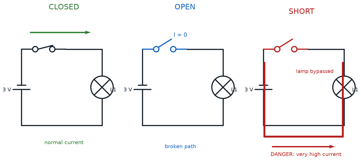
Matched battery-and-lamp circuits showing a closed loop, an open switch, and a dangerous short-circuit bypass

Series and Parallel Circuit Comparison
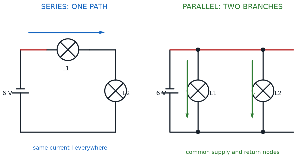
Two identical lamps connected first in one series path and then in two parallel branches

LED Forward Voltage and Current-Limiting Resistor
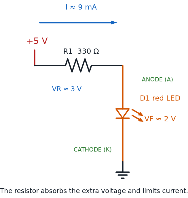
Five-volt source driving a red LED through a 330-ohm resistor with voltage drops, polarity, and current direction labeled

Fuse and Reverse-Polarity Protection Circuits
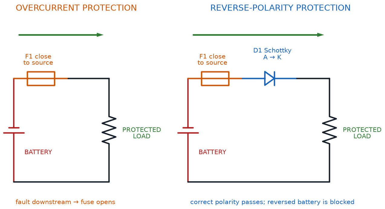
Low-voltage circuits showing a source-adjacent fuse and a fused series Schottky diode that blocks reversed battery current

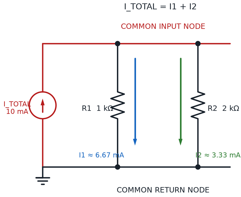
Two-Branch Current Divider

Ten-milliamp source dividing between one-kilohm and two-kilohm parallel branches with branch currents labeled

Battery EMF and Internal Resistance Model
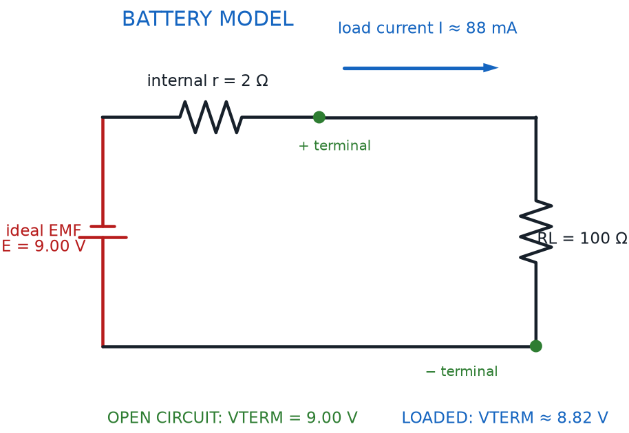
Ideal battery EMF source and internal resistance feeding a load with open-circuit and loaded terminal voltages marked

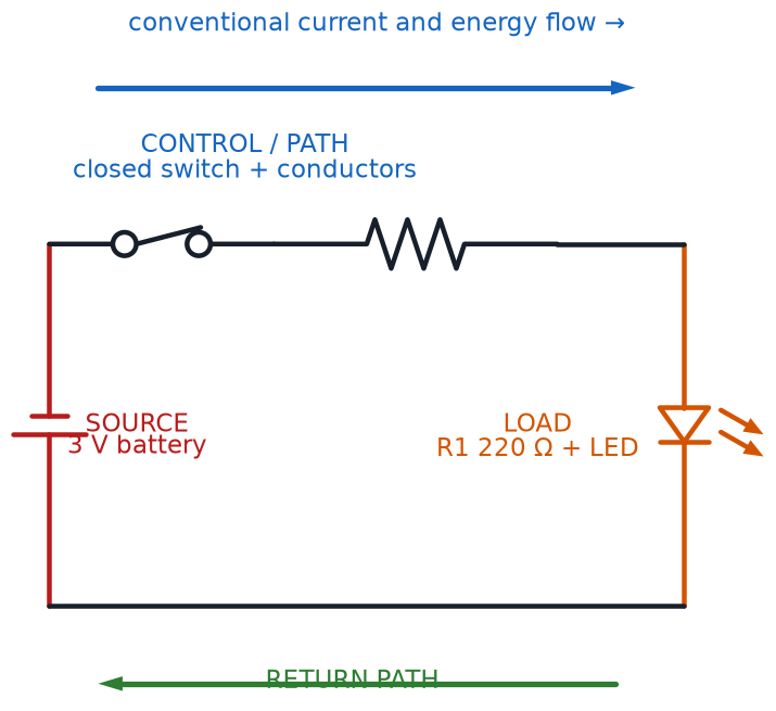
Source-Path-Load Circuit System

Battery source, closed switch and wiring path, resistor-and-LED load, and return path labeled as one circuit system

Power-to-Load Troubleshooting Test Points
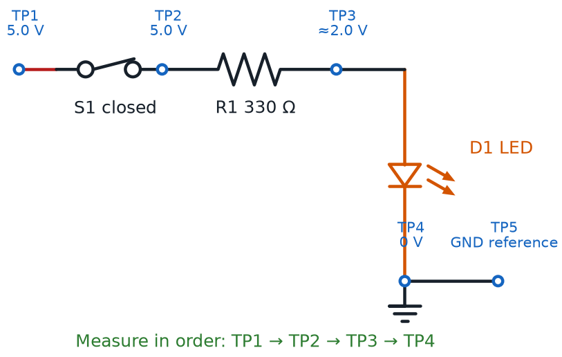
Source-switch-resistor-LED circuit with five numbered voltage test points progressing from the supply to the ground reference

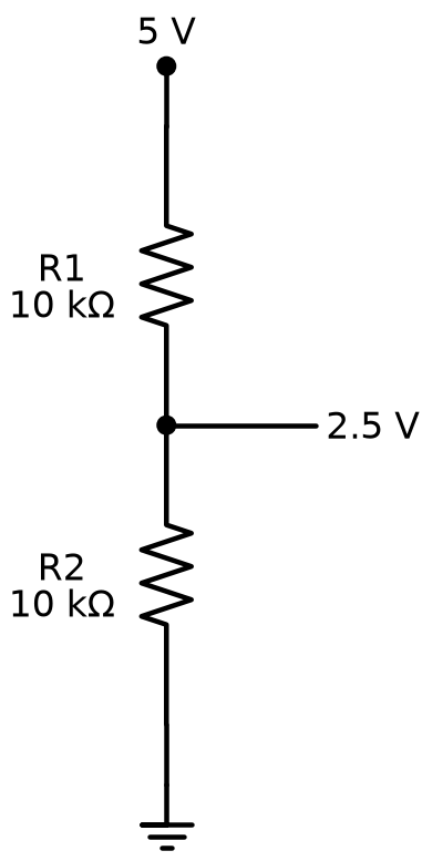
Voltage Divider Circuit

A 5-volt voltage divider made from two 10-kilohm resistors in series, with a 2.5-volt center tap

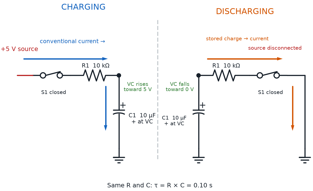
RC Charging and Discharging Circuit

Matched RC circuits showing current charging a polarized capacitor from five volts and discharging it through the same resistor

Rheostat and Thermistor Control Circuits
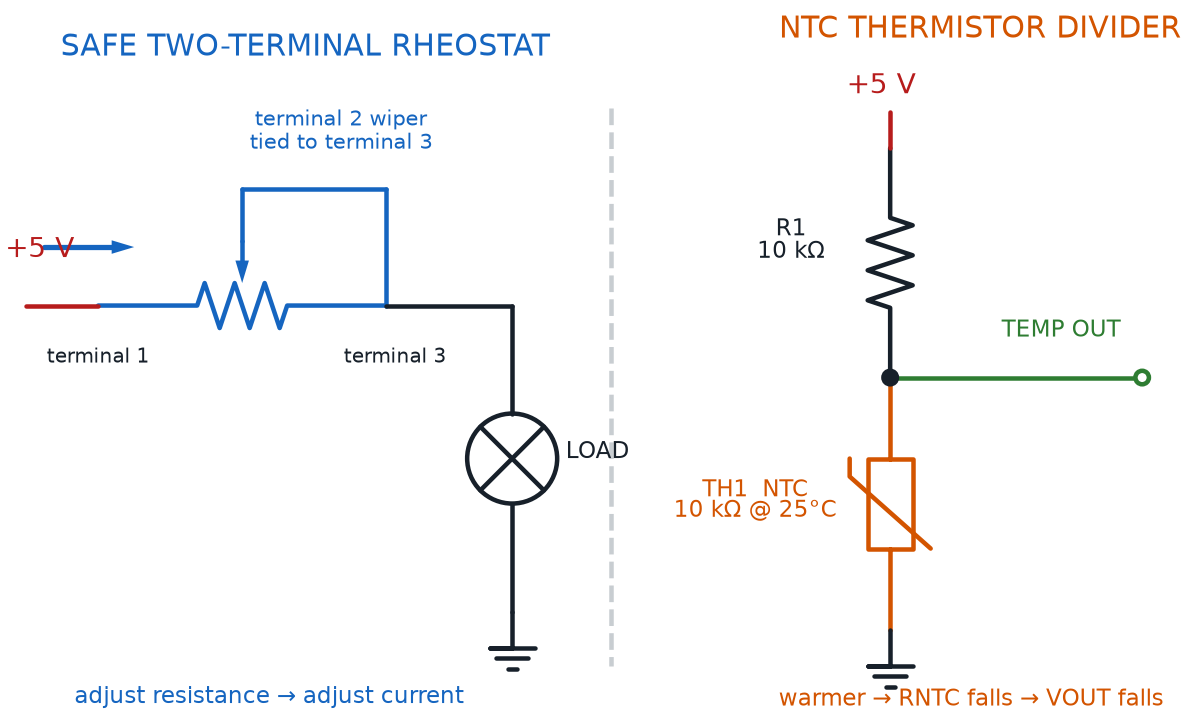
Potentiometer wired as a safe two-terminal rheostat beside an NTC thermistor voltage divider with its output node

Bypass Capacitor Across IC Power Pins
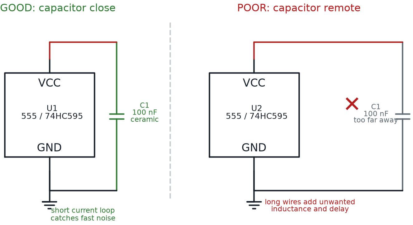
Correct 100-nanofarad ceramic bypass capacitor beside an IC compared with a crossed-out remote capacitor on long wires

Rectifier, Flyback, and Zener Diode Circuits
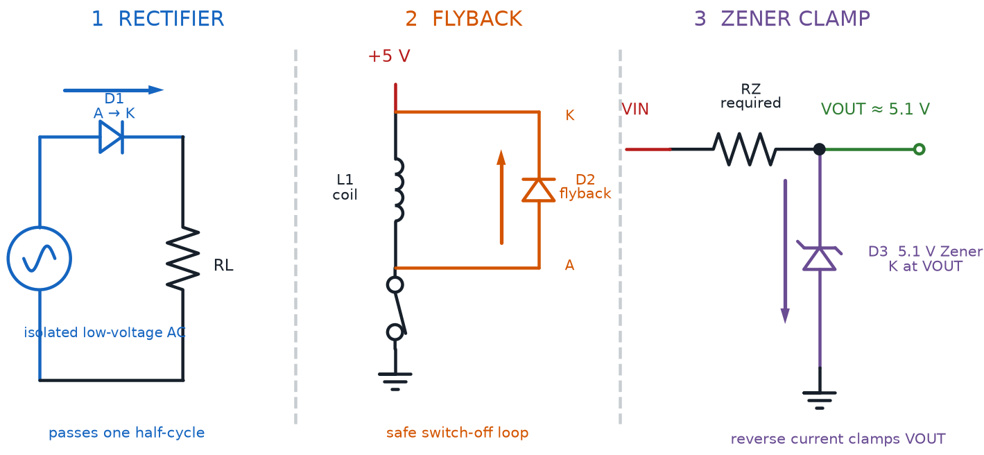
Three diode applications showing a half-wave rectifier, a flyback loop around a coil, and a series-resistor Zener clamp

Potentiometer as an Adjustable Voltage Divider
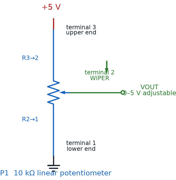
Ten-kilohm potentiometer with its end terminals across five volts and ground and its wiper producing an adjustable output

NPN Low-Side and PNP High-Side Switches
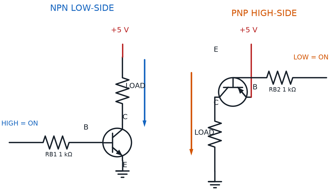
Matched NPN low-side and PNP high-side transistor switches with loads, base resistors, terminals, control polarity, and current arrows

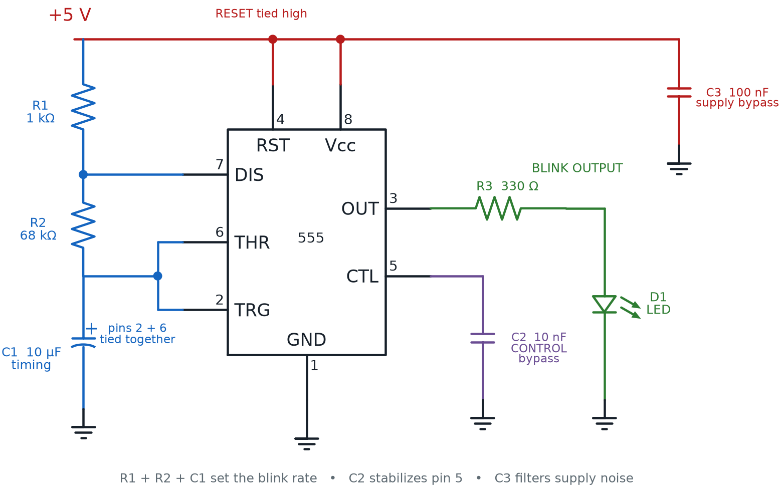
555 Timer Astable LED Circuit

Complete 555 astable circuit with pins 2 and 6 tied to the R1, R2, and C1 timing network; reset tied high; control and supply bypass capacitors; and an LED with a series resistor on pin 3

555 LED Blinker and Buzzer Driver Circuits
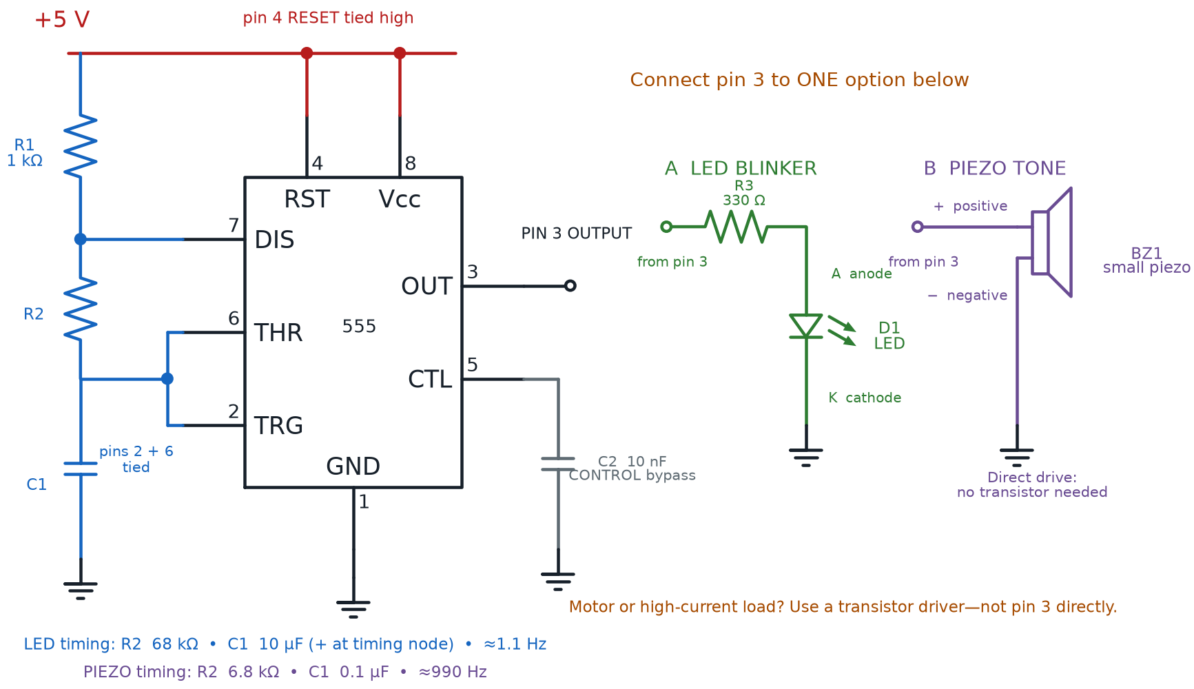
Shared 555 astable timing core beside two alternative pin 3 outputs: a current-limited LED with anode and cathode marked, and a directly driven polarized small piezo buzzer

RC Push-Button Debounce Circuit

Two states of an active-low RC push-button debounce circuit: released with the capacitor charging through a 10-kilohm pull-up resistor, and pressed with the capacitor discharging through the closed button to ground

Light Detector and Dark Detector Voltage Dividers
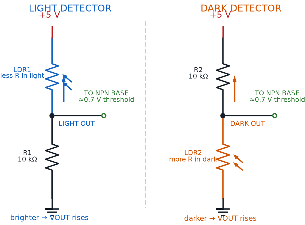
Photoresistor-above and photoresistor-below voltage dividers showing how light or darkness raises the transistor input voltage

Common-Cathode and Common-Anode RGB LED Wiring
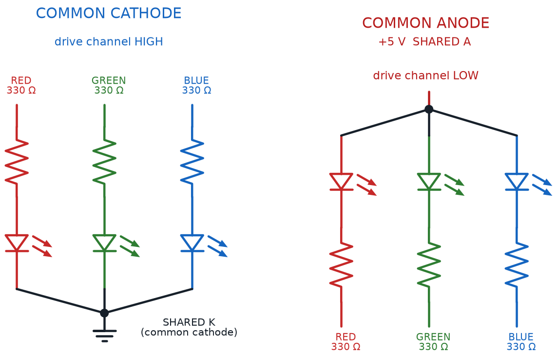
Common-cathode and common-anode RGB LED packages with one resistor per color channel and opposite drive polarities

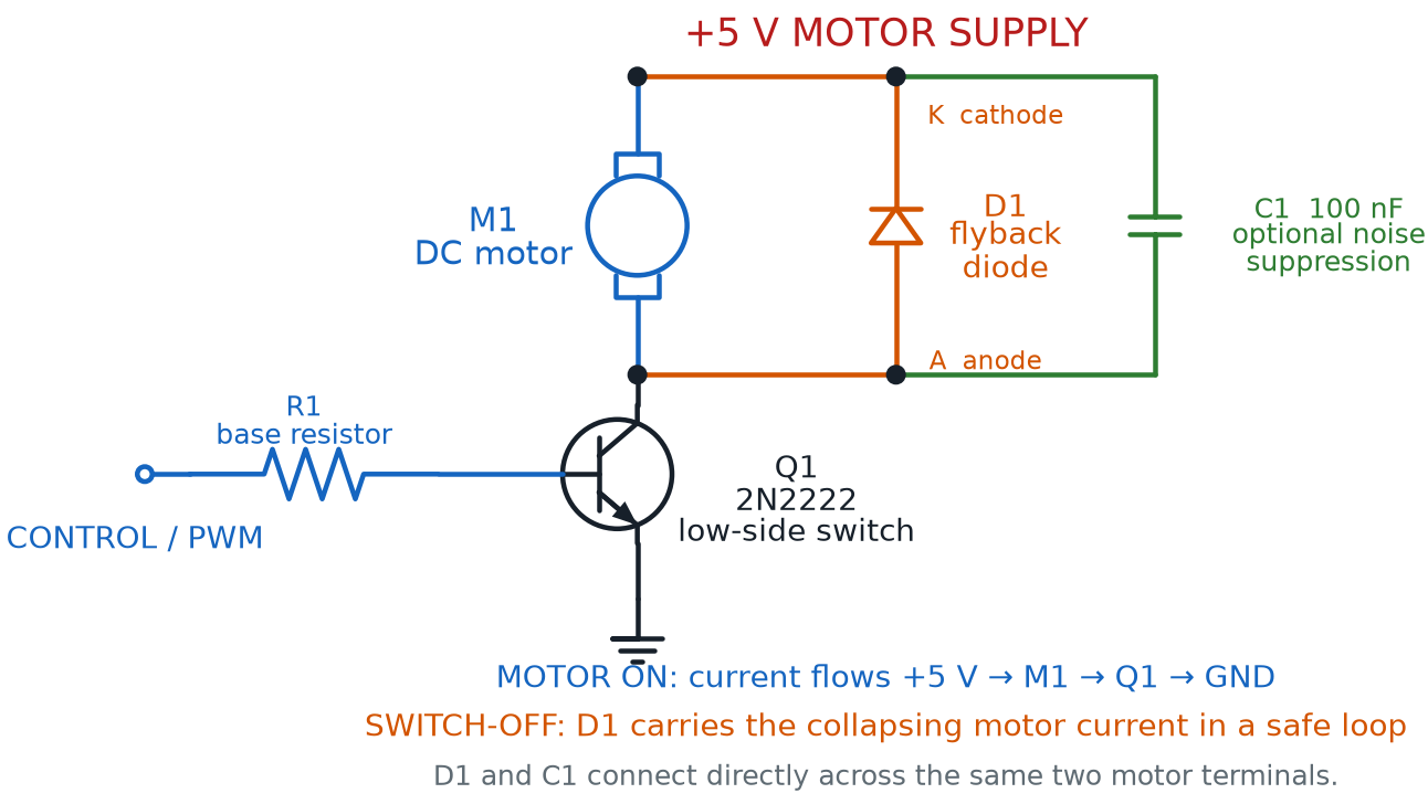
Protected Transistor Motor Driver

Protected NPN low-side motor driver with a base resistor, flyback diode whose cathode connects to positive 5 volts, and an optional suppression capacitor across the motor

Active and Passive Buzzer Driver Circuits
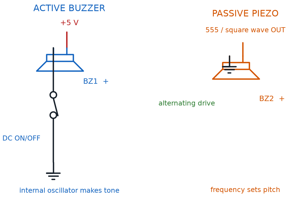
Vertically connected active buzzer on switched DC beside a passive piezo driven by a 555 square-wave output

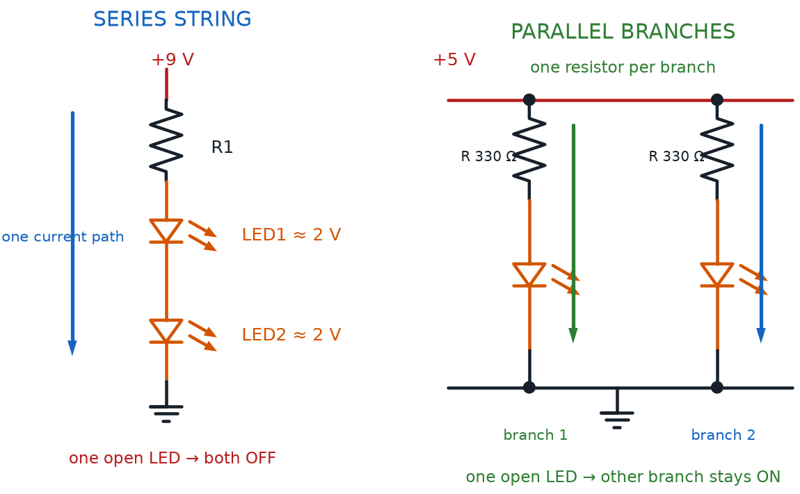
Series and Parallel LED Wiring

Two LEDs in one series string compared with two separately resisted parallel LED branches and open-failure behavior

Voltage, Current, and Resistance Measurement Connections
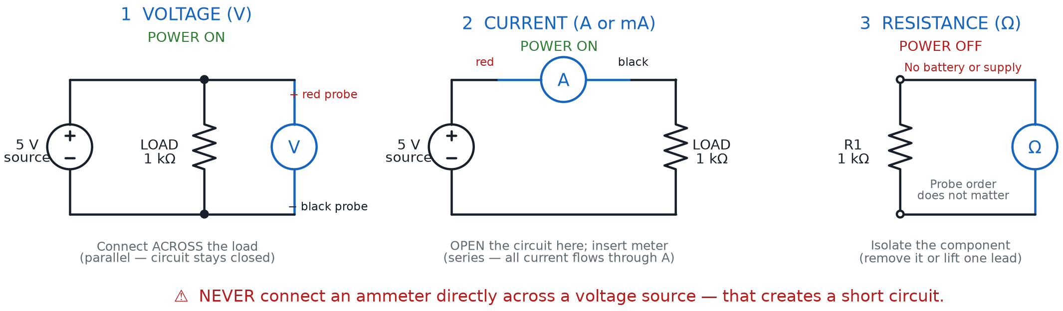
Three multimeter connection diagrams showing a voltmeter in parallel across a powered load, an ammeter inserted in series, and an ohmmeter across an isolated unpowered resistor

Healthy, Open, and Shorted Circuit Measurements
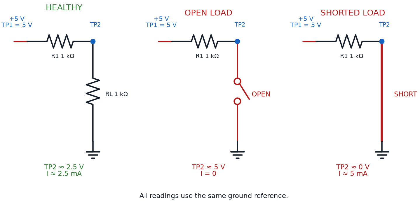
The same five-volt resistor-load circuit shown healthy, with an open load, and with a shorted load, using consistent test points and predicted voltages

Linear, Buck, and Boost Regulator Topologies
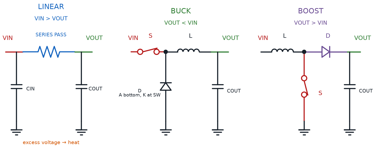
Simplified linear, buck, and boost regulator schematics with their pass element, switches, diodes, inductors, capacitors, and voltage relationships labeled

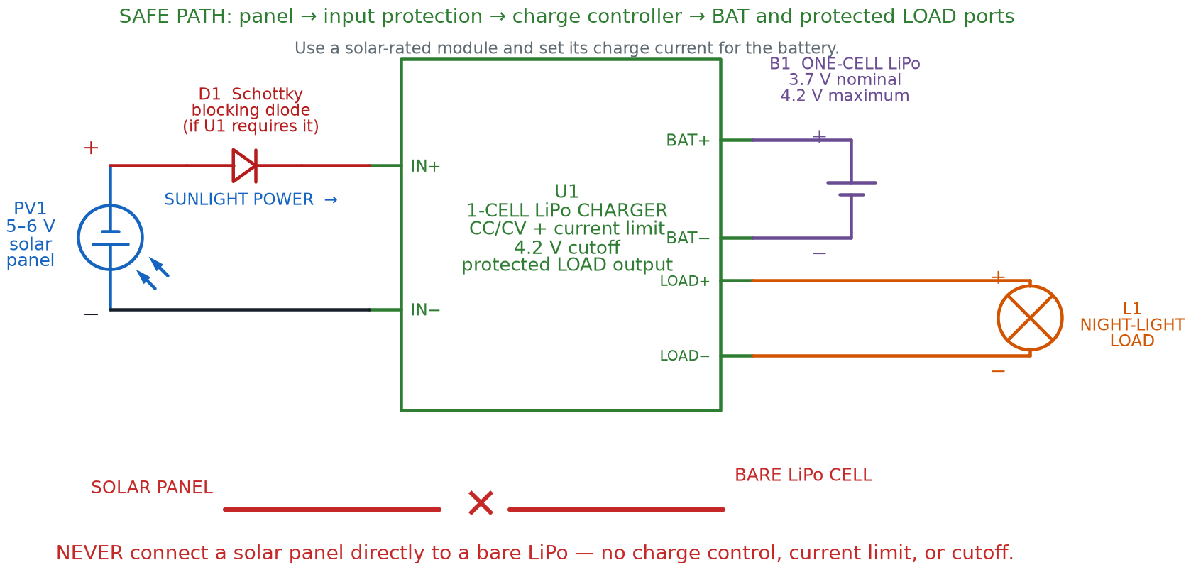
Solar Panel LiPo Charging Circuit

Safe solar charging path from a 5-to-6-volt panel through a conditional Schottky blocking diode and a protected single-cell LiPo charge controller to separate battery and night-light load ports, with direct panel-to-bare-cell wiring crossed out

Solar Cells in Series and Parallel

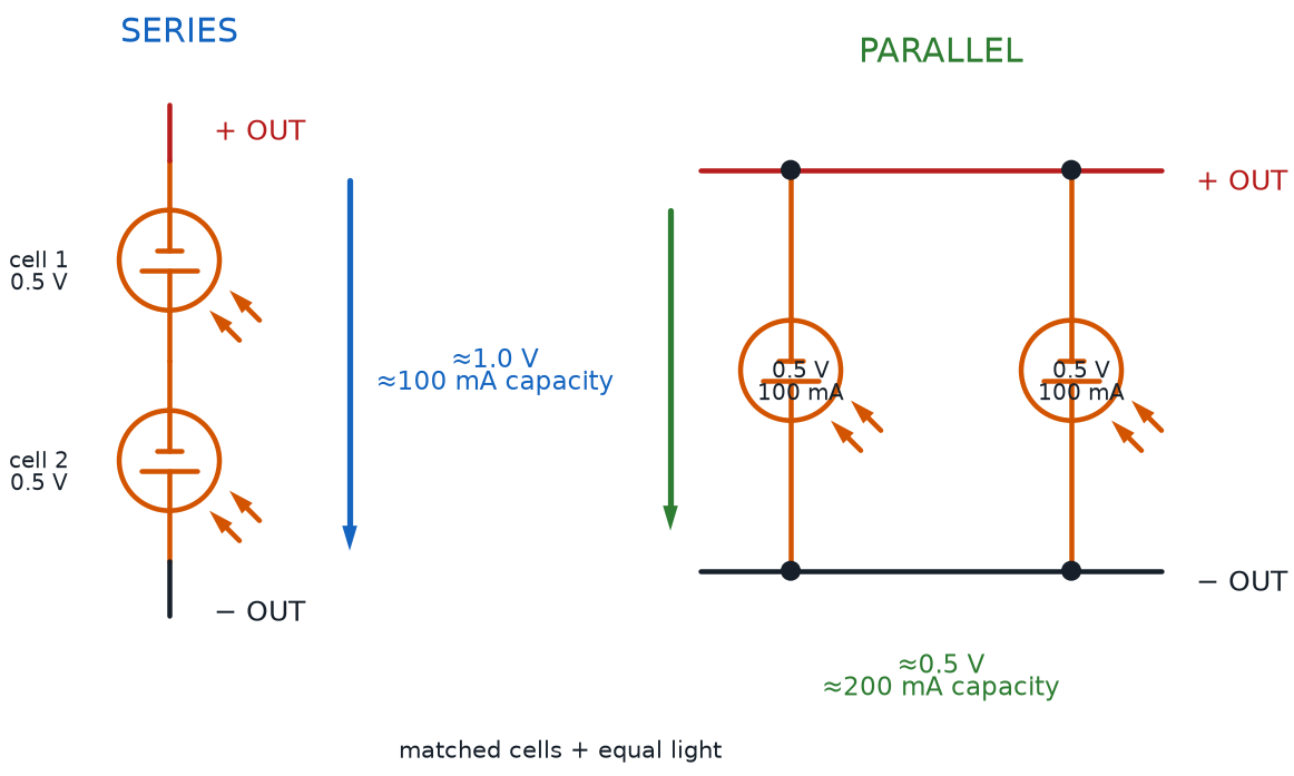
Matched solar cells connected in series to add voltage and in parallel to add current capacity

Transistor NOT, NAND, and NOR Gates

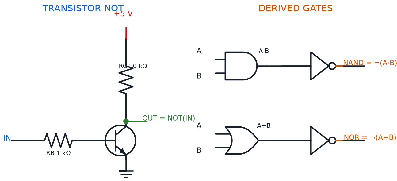
Complete NPN transistor inverter followed by block-level AND-then-NOT NAND and OR-then-NOT NOR signal paths

Cross-Coupled NAND RS Latch

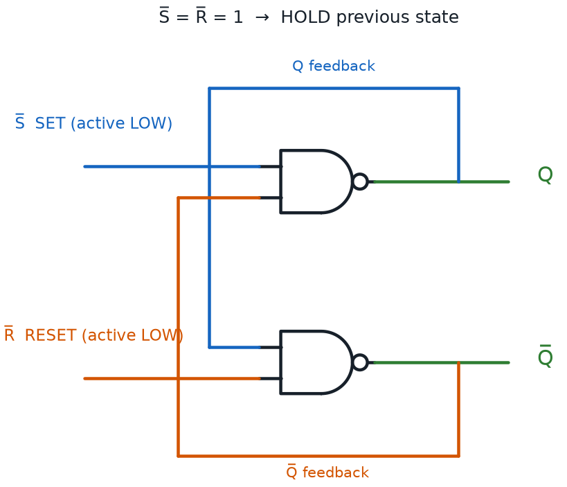
Two NAND gates cross-coupled with separate Q and Q-bar feedback paths and active-low Set and Reset inputs

RC Timer, 555 Oscillator, and Signal Generator
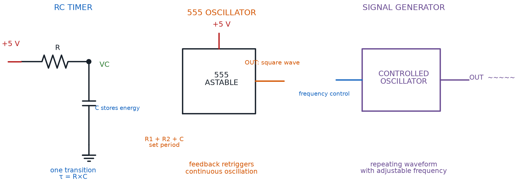
Simplified RC timing circuit, 555 astable oscillator, and controlled signal generator showing the progression from one transition to continuous waveforms