RGB LED Circuit
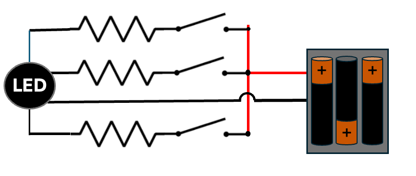
The goal of this circuit is to connect up a RGB LED so that when you press one of three momentary switch buttons, one of the three LEDs will light up.
Circuit Diagram
This LED is a common cathode circuit. The GND pin goes to the lower ground rail and each of the LED pins are routed through a resistor and a momentary switch on the breadboard. The resistors are calibrated so that the brightness of each of the LEDs is balanced.
The top rail is +5v.