Raspberry Pi RGB Box
Welcome, Maker!
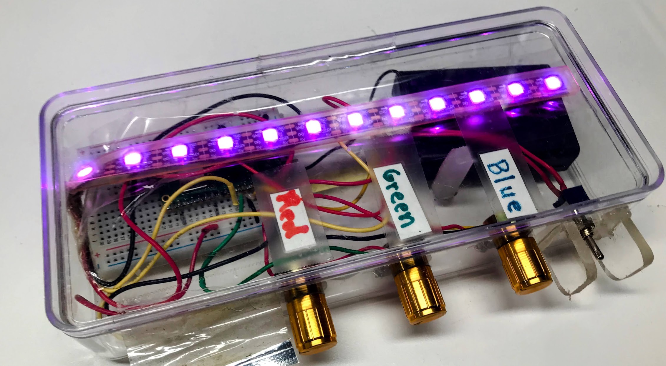
 In this project you will build a color-mixing box with three knobs and a strip
of colorful lights. Turn the knobs to blend red, green, and blue into any color
you can imagine. Let's build something amazing!
In this project you will build a color-mixing box with three knobs and a strip
of colorful lights. Turn the knobs to blend red, green, and blue into any color
you can imagine. Let's build something amazing!
This project uses three potentiometers (turning knobs) and a strip of NeoPixel LEDs. Each knob controls one color: red, green, or blue. Turn a knob up and that color gets brighter. Mix all three together and you can make millions of different colors!
We take this box to science fairs and let kids as young as three play with it. When they turn the knobs and the lights change, we say "Hey, you're a programmer!"
What You Will Learn
- How to read a potentiometer with an Analog-to-Digital Converter (ADC).
- How to control NeoPixel LED colors with RGB values.
- How to map a sensor reading to a color value.
- How to build a fun, interactive hardware project.
Parts List
| Quantity | Part | Approximate Cost |
|---|---|---|
| 1 | Raspberry Pi Pico with headers | $4 |
| 1 | Half-size solderless breadboard | $2 |
| 3 | 10KΩ linear potentiometers | $2 |
| 1 | NeoPixel LED strip with 10 pixels | $2 |
| 1 | 3×AA battery case with on/off switch | $2 |
| 1 | Clear plastic project box | $4 |
| 1 roll | 22-gauge solid hookup wire | $3 |
| 1 | USB cable (Micro-B to USB-A) | — |
Total cost: about $15. If you buy parts in batches of ten, you can get this under $10 per kit.
Required Tools
- Solderless breadboard — to connect the components without any soldering.
- Jumper wires — to run connections between the breadboard and the Pico.
- USB cable (Micro-B to USB-A) — to power the Pico and upload your code.
How It Works
Potentiometers
A potentiometer (pot for short) is a turning knob that acts like an adjustable resistor. It has three wires:
- One wire goes to power (3.3V on the Pico).
- One wire goes to ground (GND).
- The middle wire is the signal wire — its voltage changes as you turn the knob.
When the knob is all the way to the left, the signal wire reads 0 volts. When the knob is all the way to the right, it reads 3.3 volts. Anywhere in between gives a value in between.
The Pico's Analog-to-Digital Converter (ADC) reads that voltage and turns it into a number between 0 and 65535.
NeoPixels
A NeoPixel is a smart LED with a tiny chip inside. You only need one wire to control it — a data wire from the Pico. Each NeoPixel can show any color using an RGB value: three numbers, each from 0 to 255, for red, green, and blue.
(255, 0, 0)= full red.(0, 255, 0)= full green.(0, 0, 255)= full blue.(255, 255, 255)= white (all three at full brightness).(0, 0, 0)= off.
Key Idea: Scaling Numbers
 The ADC gives us numbers from 0 to 65535, but NeoPixels need numbers from
0 to 255. We can scale down by shifting the bits right by 8 — that divides
the number by 256. It is a fast way to shrink the range.
The ADC gives us numbers from 0 to 65535, but NeoPixels need numbers from
0 to 255. We can scale down by shifting the bits right by 8 — that divides
the number by 256. It is a fast way to shrink the range.
Wiring
Pico Pin Reference
| Pin Name | GPIO Number | What Connects Here |
|---|---|---|
| GP0 | GPIO 0 | NeoPixel data wire |
| GP26 | GPIO 26 (ADC0) | Red knob signal |
| GP27 | GPIO 27 (ADC1) | Green knob signal |
| GP28 | GPIO 28 (ADC2) | Blue knob signal |
| 3V3 | 3.3V power | All three pot power wires, NeoPixel VCC |
| GND | Ground | All three pot ground wires, NeoPixel GND |
Step-by-Step Wiring
Red potentiometer (left knob):
- Place the potentiometer across the center gap of the breadboard.
- Connect the left pin to a 3.3V pin on the Pico with a jumper wire.
- Connect the right pin to a GND pin on the Pico with a jumper wire.
- Connect the middle pin (the wiper) to GP26 (ADC0) with a jumper wire.
Green potentiometer (middle knob):
- Place it on the breadboard next to the red pot.
- Left pin → 3.3V on the Pico.
- Right pin → GND on the Pico.
- Middle pin → GP27 (ADC1).
Blue potentiometer (right knob):
- Place it on the breadboard next to the green pot.
- Left pin → 3.3V on the Pico.
- Right pin → GND on the Pico.
- Middle pin → GP28 (ADC2).
NeoPixel strip:
- Connect the VCC (power) wire on the strip to a 3.3V pin on the Pico.
- Connect the GND wire on the strip to a GND pin on the Pico.
- Connect the Data In wire on the strip to GP0 on the Pico.
Monty's Tip
 NeoPixel strips have a direction arrow printed on them. Make sure the data
wire connects to the Data In end (the arrow points away from the Pico),
not the Data Out end.
NeoPixel strips have a direction arrow printed on them. Make sure the data
wire connects to the Data In end (the arrow points away from the Pico),
not the Data Out end.
Lab 1: Test the NeoPixel
Before wiring all three knobs, check that your NeoPixel strip is connected correctly. This short program blinks the last pixel on the strip red. If you see it blinking, your strip is working!
Save this file as 01-blink.py on your Pico and run it.
1 2 3 4 5 6 7 8 9 10 11 12 13 14 15 16 17 18 19 20 | |
What each line does:
| Line | What it does |
|---|---|
from machine import Pin |
Loads the Pin class so we can use GPIO pins |
from neopixel import NeoPixel |
Loads the NeoPixel driver |
NEOPIXEL_PIN = 0 |
Stores the GPIO number in a named variable |
strip = NeoPixel(Pin(0), 10) |
Creates a strip object for 10 pixels on pin 0 |
strip[9] = (255, 0, 0) |
Sets the color of pixel 9 (the last one) to red |
strip.write() |
Sends all color values to the strip over the data wire |
Expected result: The last LED on the strip blinks red on and off. If nothing blinks, double-check that your Data In wire is on GP0 and that VCC and GND are correct.
Lab 2: RGB Color Mixer
Now add the three potentiometers and run the main program. Each knob controls one color channel — turn them to mix any color you like.
Save this file as main.py on your Pico.
1 2 3 4 5 6 7 8 9 10 11 12 13 14 15 16 17 18 19 20 21 22 23 24 25 26 27 28 29 30 31 32 33 34 35 36 | |
What each section does:
| Section | What it does |
|---|---|
pot_red = ADC(26) |
Creates an ADC reader on GPIO 26 for the red knob |
pot_red.read_u16() |
Reads a 16-bit value (0–65535) from the pot |
>> 8 |
Shifts the bits right by 8, scaling 0–65535 down to 0–255 |
for i in range(NUMBER_PIXELS) |
Loops through every pixel index (0 through 9) |
strip[i] = (red, green, blue) |
Sets pixel i to the current color mix |
strip.write() |
Sends all the updated colors to the strip at once |
led.toggle() |
Flips the onboard LED — a quick heartbeat to show things are running |
Try It Out
Once the program is running, open the Thonny Shell (or REPL). You will see lines like this appearing every 1/20 second:
1 2 3 4 | |
Try these experiments:
- Pure colors — Turn the red knob all the way up and keep green and blue at zero. You should see bright red.
- Yellow — Turn red and green all the way up, and blue all the way down. Red + green = yellow!
- White — Turn all three knobs all the way up.
- Off — Turn all three knobs all the way down.
- Your own color — Find a color you like and write down the R, G, B numbers from the console.
Challenges
- Fewer pixels — Change
NUMBER_PIXELSto 5. Only half the strip lights up. Can you explain why? - Pattern mode — Instead of setting every pixel the same color, make a gradient: set the first pixel brighter and the last pixel dimmer. Hint: multiply the color by
i / NUMBER_PIXELS. - Speed control — Add two buttons and use them to control
sleep()time. Now you have a speed knob. - Save a color — Add a button. When you press it, print the current R, G, B values to the console or a display.
- Add a display - add a low-cost LCD display like this video which displays the values of the Red, Green and Blue potentiometers.
You Built a Color Mixer!
 You just built an interactive hardware project that reads three sensors and
controls ten lights in real time. That is real embedded programming! Next,
try adding a button to save your favorite colors, or explore the
NeoPixel patterns lab to add animations.
You just built an interactive hardware project that reads three sensors and
controls ten lights in real time. That is real embedded programming! Next,
try adding a button to save your favorite colors, or explore the
NeoPixel patterns lab to add animations.