Appendix A: The I2C Bus
By the end of this appendix you'll be able to:
- Explain how the Pico uses two wires to talk to many chips, and how it picks one chip by its address
- Turn the raw bytes from a sensor into a real number with Python
- Describe how the Pico takes turns with five devices, and why a slow display can delay the sensors
A robot is full of small chips. One feels motion. One finds north. One measures distance. One watches the battery. One drives a screen. Each chip needs to talk to the Pico. But the Pico only has so many pins. This appendix shows the trick that lets one Pico talk to dozens of chips using just two wires.
Welcome to the I2C Bus!
 Today you will peek inside a robot and watch its chips talk, one polite turn at a time. You will scan a bus, read raw bytes, and see why a screen can slow down a sensor. Let's build something amazing!
I2C in One Minute
Here is the whole idea at a glance. Every term in this table gets its own explanation below.
| Question | Answer |
|---|---|
| What is it? | A two-wire bus that connects the Pico to many small chips |
| What are the wires? | Serial Clock (SCL) and Serial Data (SDA) |
| Who is in charge? | One controller (your Pico). It starts every conversation |
| How does it pick a chip? | Every chip has a 7-bit address. The controller says the address first |
| How does a chip say "yes"? | It pulls SDA low for one clock pulse. That is an acknowledge (ACK) |
| Can two chips talk at once? | No. There is one conversation at a time, so the Pico takes turns |
| How fast? | 100,000 or 400,000 bits per second on most boards |
I2C is short for Inter-Integrated Circuit. You say it "eye-squared-see". Philips (now NXP) invented it in the early 1980s. Chapter 8 introduced I2C. This appendix goes much deeper. The Protocol Comparison Explorer MicroSim shows how I2C compares with SPI and UART.
1. What Is a Bus?
Picture a classroom where the teacher asks questions. Every student hears every question. But each question starts with a name: "Maya, what is 7 times 8?" Only Maya answers. Everyone else stays quiet and listens for their own name.
A bus works the same way. It is a set of shared wires that many chips connect to. Every chip hears everything the Pico sends. Each message starts with an address. Only the chip that owns that address answers.
Why share wires instead of giving every chip its own? Count the pins.
| Connection | Signal wires | Chips on the same wires | Typical use |
|---|---|---|---|
| I2C | 2 (SDA, SCL) | up to 112 | sensors, small displays, clocks |
| SPI | 3, plus 1 more for each chip | a few | fast displays, SD cards |
| UART | 2 for each pair of chips | exactly 2 | GPS, serial consoles |
With I2C you can add a sixth, seventh or tenth chip. The Pico still uses the same two pins. That is why robots, phones and laptops are full of I2C.
2. Meet the Hardware
The robot in this appendix uses the parts below. The table lists each chip, what it does, and its address. The five-device MicroSim near the end uses everything except the compass.
| Device | Chip (breakout board) | What it does | I2C address |
|---|---|---|---|
| Accelerometer | MPU-6050 (GY-521) | feels pushes and gravity | 0x68 |
| Gyroscope | MPU-6050 (same chip) | feels how fast the robot turns | 0x68 |
| Compass | HMC5883L (GY-271) | senses Earth's magnetic field | 0x1E |
| Distance sensor | VL53L0X | times a pulse of light to an obstacle | 0x29 |
| Battery monitor | INA219 | measures battery voltage and current | 0x40 |
| Display | SSD1306 128x64 OLED | shows text and pictures | 0x3C |
(OLED stands for organic light-emitting diode. It is a screen where every pixel makes its own light.)
The accelerometer and the gyroscope are one chip with one address. They are two
sensors, but only one device on the bus. Leave out the compass and the other five
functions need just four addresses: 0x68, 0x29, 0x40 and 0x3C. Add the
compass back and you have five addresses for six functions.
Chapter 10 shows the MPU-6050 and the compass. Chapter 9 covers the VL53L0X distance sensor. Chapter 15 sets up the OLED display.
Parts notes: read these before you buy
- Compass clones. Many boards sold as "GY-271 / HMC5883L" now hold a different chip, the QMC5883L. It answers at
0x0D, not0x1E. Some hold a QMC5883P at0x2C. An I2C scan tells you in seconds which chip you have. The code for each chip is different. - Combo boards. Some boards put an MPU-6050 and an HMC5883L together (GY-86 and GY-87). The compass hangs off the MPU-6050's own private bus. To see it from the Pico, turn on the MPU-6050's bypass mode. That is bit 1 of register
0x37. - Age. The MPU-6050 and HMC5883L are older parts. They are cheap and well documented, so they are great for learning. Check that you can still buy them before you design a product around them.
Wire the Bus
Every device connects to the same four lines. Wiring a new device means adding one more set of wires to the same rows. Follow these steps in order.
- Unplug the Pico from USB.
- Connect Pico pin 36 (3V3 OUT) to the VCC pin of every board. All the boards run on 3.3 volts.
- Connect Pico pin 38 (GND) to the GND pin of every board.
- Connect Pico pin 1 (GP0) to the SDA pin of every board.
- Connect Pico pin 2 (GP1) to the SCL pin of every board.
- Add one board at a time. Run the scanner (see Section 5) after each board. Exactly one new address should appear.
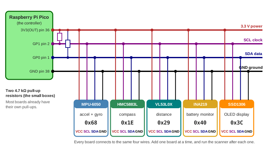
In MicroPython, I2C(0, sda=Pin(0), scl=Pin(1)) is the bus these pins belong to. The
Pico has two I2C buses. I2C0 can use GP0/GP1, GP4/GP5 and other pairs. I2C1 can use
GP2/GP3, GP6/GP7 and other pairs.
Safety first
The INA219 sits between the battery and the robot, so it handles real power. Ask an adult to help with anything that touches a LiPo battery. Never let bare battery wires touch each other.
3. Two Wires: SDA and SCL
I2C uses exactly two signal wires.
- SCL (Serial Clock) is the clock. The Pico ticks it like a metronome. One tick moves the conversation along by one bit.
- SDA (Serial Data) carries the bits, one for each tick. Bits travel both ways on this wire. Only one chip talks at a time, so the wire can be shared.
The rule for data is simple. The sender may change SDA only while SCL is low. The receiver reads SDA while SCL is high. So the bits hold still at the moment someone looks at them.
Pull-up Resistors: Why a Wire Only Goes One Way
Here is a surprise. No chip on an I2C bus may push a wire high. A chip can only pull a wire down to ground, or let go.
Imagine a spring holding a rope up. A chip can pull the rope down. When it lets go, the spring pulls the rope back up. The spring is a pull-up resistor. It is a small resistor (4,700 ohms is typical) from each wire to the 3.3 volt line. When nobody pulls, the resistor keeps the wire high. When any chip pulls, the wire goes low.
This design solves two problems:
- No short circuits. If one chip pushed high while another pulled low, they would fight. With pull-down only, the worst case is a polite tie.
- ACK works. During the ACK pulse, the Pico lets go of SDA. If a chip pulls it low, the Pico reads a 0. If nobody does, the resistor keeps it high and the Pico reads a 1.
Most breakout boards carry their own pull-up resistors, so the bus usually works with no extra parts. The Pico's built-in pull-ups are weak, so count on the ones on the boards.
START, STOP and Speed
Two special moments mark the start and end of a conversation. Both happen while SCL is high. That is normally when SDA must hold still.
- START: SDA falls while SCL is high. It means "I am about to talk."
- STOP: SDA rises while SCL is high. It means "I am done. The bus is free."
Most boards run the bus at 100,000 bits per second (standard mode). Some run it at
400,000 bits per second (fast mode). MicroPython uses 400,000 unless you pass a
different freq.
Controller and target
Older books call the Pico the "master" and the chips "slaves". Since Revision 7.0 (2021), the official I2C specification from NXP says controller and target. The MicroPython documentation says controller and peripheral. This appendix uses controller and target.
4. Anatomy of a Transaction
Every conversation is called a transaction. Every transaction follows the same script:
- The controller sends START.
- The controller sends the address. That is 7 bits, then one R/W bit. A 0 means "I will write to you." A 1 means "I want to read from you."
- The target that owns the address sends an ACK. If nobody does, the controller sees a NACK and knows nobody is home.
- Data bytes follow, 8 bits each. After every byte, the receiver sends an ACK to say "got it."
- The controller sends STOP.
Every byte takes 9 clock pulses. That is 8 bits plus 1 ACK bit. Remember "nine bits per byte." You will use it to work out how long things take.
Reading from a chip takes two steps. The chip first needs to know which of its
numbers you want. The diagram shows a real read of the MPU-6050's identity register,
0x75.
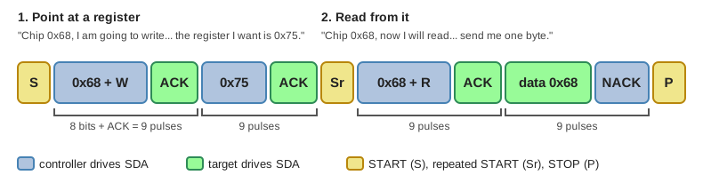
Look at the colors. Blue boxes come from the controller. Green boxes come from the target. The target only speaks for the ACKs and the data byte.
Notice the repeated START (Sr). The controller does not let go of the bus between "point at a register" and "read from it." It starts again right away. No other controller can slip in between.
The last byte ends with a NACK from the controller. That is not an error. It means "that was the last byte I want." The target stops driving SDA so the controller can send STOP.
Why Two Devices Never Get Confused
The diagram above shows one target. Real buses usually carry several. Here is the question that trips people up: if a target like an EEPROM gets sent a data byte that happens to match some other chip's address, does that other chip wake up and answer by mistake?
No -- and the reason is timing, not luck. A target only compares a byte to its own address immediately after a START or repeated START. The moment the address byte does not match, a target stops listening and ignores every byte that follows, no matter what it contains, until the bus sees a START again. So an EEPROM's internal memory address can never be mistaken for another chip's device address, even if the numbers collide, because the chip that did not match already dropped off the bus.
How to use this MicroSim: Press Next or Play to step through a real
transaction, byte by byte: a controller writes a 16-bit memory address to an EEPROM at
0x50, then reads one byte back, while an LCD backpack at 0x27 shares the same wires.
Watch the LCD panel switch to "ignoring the bus" right after the first address byte --
and stay that way through both memory-address bytes -- until the repeated START wakes it
up to check again.
Explore the I2C Start Bit and Address Framing MicroSim
5. Addresses and the I2C Scanner
Seven address bits give 128 possible addresses, 0x00 to 0x7F. Sixteen are reserved
for special jobs (0000 XXX and 1111 XXX in the I2C specification). That leaves
0x08 to 0x77, or 112 usable addresses. Chapter 8 says "up to 127 devices". That
is the number of addresses a 7-bit number can hold. The scanner only asks the 112 that
chips are allowed to use.
Here are our devices written three ways:
| Device | Hex | Decimal | 7-bit binary |
|---|---|---|---|
| HMC5883L compass | 0x1E |
30 | 0011110 |
| VL53L0X distance | 0x29 |
41 | 0101001 |
| SSD1306 display | 0x3C |
60 | 0111100 |
| INA219 battery | 0x40 |
64 | 1000000 |
| MPU-6050 accel + gyro | 0x68 |
104 | 1101000 |
Monty's Hex Helper

0x68 is just a number written in base 16, and the 0x means "hex". Python prints it with hex(104) and accepts it anywhere a number goes, so 0x68 == 104 is True.
Datasheets can confuse you here. The HMC5883L datasheet lists the 8-bit write address
0x3C and read address 0x3D. Those are the 7-bit address 0x1E shifted left one
place, with the R/W bit added. MicroPython uses the 7-bit address, 0x1E. (The book's
hmc5883l.py driver says address=30, which is 0x1E in decimal.) And that 0x3C is
not the SSD1306 display. The display's 7-bit address just happens to be 0x3C too.
How the Scanner Works
Run a scan the first time you use any new bus. A scan asks every address, one after
another, "is anyone there?" The MicroPython documentation says it this way. i2c.scan()
tries every address from 0x08 to 0x77. A device responds if it pulls SDA low after
its address, including the write bit, is sent.
This is the big idea: devices never announce themselves. The Pico asks. Only the owner of the address answers. Here is a complete scanner:
1 2 3 4 5 6 7 8 9 10 11 12 13 14 15 16 | |
| Line | What it does |
|---|---|
from machine import Pin, I2C |
Loads the tools for pins and for the I2C bus |
sda_pin = Pin(0) |
Names the pin that carries data (GP0) |
scl_pin = Pin(1) |
Names the pin that carries the clock (GP1) |
i2c = I2C(0, ...) |
Sets up I2C bus 0 on those pins at 400,000 bits per second |
device_list = i2c.scan() |
Asks addresses 0x08 to 0x77 and returns the ones that said ACK |
for address in device_list: |
Repeats the next line once for each chip found |
print(... hex(address) ...) |
Shows the address in hex and in decimal |
With our parts wired up, it prints Found a device at 0x1e = 30 decimal, then
0x3c = 60, then 0x68 = 104. Try it in slow motion below. Press Step to ask one
address at a time. Or slow the speed slider all the way down and follow the clock and
data traces bit by bit. Then unplug a chip and scan again.
How to use this MicroSim: Press Step or Start. Uncheck a chip to unplug it. Then press Scan again.
Explore the I2C Bus Scanner MicroSim
What If Two Chips Have the Same Address?
Then the bus cannot tell them apart. Both would answer at once. Every designer meets this problem sooner or later. There are four ways out:
| Fix | How it works | Example |
|---|---|---|
| Address pin | Many chips have a pin that changes one address bit | MPU-6050: AD0 low is 0x68, high is 0x69. INA219 breakout: jumpers A0 and A1 give 0x40, 0x41, 0x44 or 0x45 |
| Change it in software | Some chips let you write a new address, so wake them one at a time | VL53L0X: use its XSHUT pin to wake one chip at a time |
| A second bus | Use another pair of pins | The Pico has two buses: I2C0 and I2C1 |
| A multiplexer | A chip that switches the bus between several branches | TCA9548A |
Try It: A Pretend Bus
You can practice the scan loop without any chips. The program below pretends to be a
bus. A dictionary holds the chips. A loop asks every address, just like i2c.scan().
It runs on the Pico, or on any computer with Python.
What Do You Think Will Happen?
 The dictionary lists the MPU-6050 first. Before you run it, guess which device the scan prints first. Then find out!
1 2 3 4 5 6 7 8 9 10 11 12 13 14 15 16 | |
| Line | What it does |
|---|---|
pretend_bus = { ... } |
A dictionary. Each key is an address and each value is a chip name |
answered = [] |
An empty list that will hold the addresses that answered |
for address in range(0x08, 0x78): |
Counts through every address a scan asks |
if address in pretend_bus: |
Is a chip living at this address? |
answered.append(address) |
Adds the address to the list |
print(... pretend_bus[address]) |
Looks up the chip's name and prints it |
Were you right? The output is:
1 2 3 4 5 | |
The scan walks the addresses upward from 0x08. So it meets 0x1E first, no matter
how the dictionary is ordered. A real scanner always lists chips from the lowest address
to the highest.
6. Registers: The Mailboxes Inside a Chip
The address picks the chip. But a chip holds many separate numbers. It holds settings, results and an identity code. Each one lives in a numbered slot called a register. Think of the numbered lockers in a school hallway. The address chooses the hallway. The register number chooses the locker.
MicroPython gives you two helpers that do the whole "point at a register, then read" dance from the diagram in one call:
1 2 3 4 | |
| Line | What it does |
|---|---|
i2c.readfrom_mem(0x68, 0x75, 1) |
Reads 1 byte from register 0x75 of the chip at 0x68 |
who_am_i[0] |
Takes the first (and only) byte as a number |
i2c.writeto_mem(0x68, 0x6B, b'\x00') |
Writes one byte, with the value 0, into register 0x6B |
Reading the identity register is the "hello" of I2C. The MPU-6050 answers 0x68 from
its WHO_AM_I register. If you get that back, your wiring and your address are right.
Here are the registers this robot needs. You do not have to memorize them. The datasheets list the rest.
| Chip | Register | Name | What it holds |
|---|---|---|---|
MPU-6050 0x68 |
0x6B |
PWR_MGMT_1 |
write 0 to wake the chip (it powers up asleep) |
0x75 |
WHO_AM_I |
always reads 0x68 |
|
0x1C |
ACCEL_CONFIG |
accelerometer range: ±2, ±4, ±8 or ±16 g | |
0x1B |
GYRO_CONFIG |
gyroscope range: ±250 up to ±2000 degrees per second | |
0x3B-0x40 |
ACCEL_XOUT_H ... |
accelerometer X, Y, Z (high byte, then low byte) | |
0x41-0x42 |
TEMP_OUT_H ... |
chip temperature | |
0x43-0x48 |
GYRO_XOUT_H ... |
gyroscope X, Y, Z (high byte, then low byte) | |
HMC5883L 0x1E |
0x02 |
Mode | 0x00 = measure all the time (the chip powers up in single-measurement mode) |
0x03-0x08 |
Data output | compass X, Z, Y (high byte first). Yes, Z comes before Y | |
0x0A-0x0C |
ID A, B, C | 0x48, 0x34, 0x33, the letters "H43" |
|
VL53L0X 0x29 |
0xC0 |
Model ID | reads 0xEE |
0x1E |
Range result | the distance in millimeters, 16 bits | |
INA219 0x40 |
0x02 |
Bus voltage | battery voltage (see Section 7) |
0x01 |
Shunt voltage | tiny voltage across the shunt resistor (10 microvolts per step) | |
0x04 |
Current | amps, after you write a calibration number to 0x05 |
|
SSD1306 0x3C |
control byte | 0x00 or 0x40 |
the byte after the address says "commands follow" (0x00) or "pixels follow" (0x40) |
A common mistake: the MPU-6050 starts in sleep mode. In sleep mode every reading is
zero. If your accelerometer prints all zeros, write 0 to register 0x6B first.
The VL53L0X is a laser distance sensor with a long start-up recipe of dozens of register
writes. The book's VL53L0X.py driver does that recipe for you. You will use it in
Section 10. The I2C part, reading two bytes, is the easy part.
7. From Bytes to Numbers
A register is only 8 bits wide. A sensor reading needs more detail than that. So the chips use two bytes for each reading. They send the high byte first. The MPU-6050, HMC5883L, INA219 and VL53L0X all do this. To rebuild the number, shift the high byte left 8 places. Then OR the low byte in:
1 | |
There is one more trick. An accelerometer feels pushes in both directions, so the
number can be negative. Chips store negative numbers in a format called two's
complement. A 16-bit number from 0x8000 upward means "negative." To convert it,
subtract 65,536:
1 2 | |
In MicroPython, struct.unpack('>hhh', data) does both steps for three readings at once.
The > means "high byte first." The h means "signed 16-bit number."
Next, turn the raw count into a real unit. The scale depends on the range you picked in the config register:
| Sensor | Setting | Raw counts for each unit |
|---|---|---|
| Accelerometer | ±2 g (default) | 16,384 per g |
| ±4 g / ±8 g / ±16 g | 8,192 / 4,096 / 2,048 per g | |
| Gyroscope | ±250 °/s (default) | 131 per degree per second |
| ±500 / ±1000 / ±2000 °/s | 65.5 / 32.8 / 16.4 | |
| Compass | ±1.3 gauss (default) | 1,090 per gauss |
| Battery (INA219) | bus voltage | shift right 3 bits, then 4 millivolts per step |
| Distance (VL53L0X) | already millimeters |
(A "g" is the pull of gravity. At rest, an accelerometer reads 1 g straight down.)
The INA219 needs an example. Say the two bytes from register 0x02 are 1F A0.
Together that is 0x1FA0, or 8096. The lowest three bits are status flags, not
voltage. So shift them away: 8096 >> 3 is 1012. Each step is 4 millivolts, so
1012 × 0.004 is 4.048 volts. That is a nearly full LiPo battery. The chip never says
"percent." Your program has to look the voltage up in a battery curve itself.
Learning Check: The Robot That Brakes at 3.9 g
Spot the Bug!
 The robot is braking gently, but this program says 3.89 g. That would squash a real robot! The bytes are right, but the program forgot that readings can be negative. Fix it so it prints about -0.11 g.
1 2 3 4 5 6 7 8 | |
Run it first. It prints raw number: 63781 and acceleration: 3.89 g. Hint: a 16-bit
number of 0x8000 (32,768) or more is really a negative number. Add an if check
before the line that works out accel_g.
Show me the fix (try it yourself first!)
Add these two lines right after raw_value is built:
1 2 | |
Now raw number is -1755. And -1755 divided by 16,384 is about -0.11 g.
Put It to Work: A Collision-Avoidance Robot
You can now read a distance from the VL53L0X. Next, use it. In this MicroSim, a robot drives around an arena with only one sensor. The Pico reads the distance over I2C again and again. When the wall is 15 centimeters away or closer, the robot backs up 20 centimeters. Then it flips a coin and turns left or right.
How to use this MicroSim: Press Start. Watch the I2C log and the two data bytes. Then set Reads per second to 1 and Robot speed to 40.
Explore the I2C Collision-Avoidance Robot MicroSim
Find the line in the log marked TOO CLOSE!. The two bytes on that line are the sensor's
answer. Join them and you get millimeters. For example, 00 94 is 0x0094, which is 148
millimeters, or 14.8 centimeters. That is under 15, so the robot backs up.
The robot only knows the distance when a read finishes. Between reads, it drives blind. At 20 cm per second and 10 reads per second, the robot moves 2 cm between reads. That is safe. At 40 cm per second and 1 read per second, it moves 40 cm between reads. Then it bumps the wall. Speed divided by reads per second tells you how far the robot goes before it can react.
The code is short. The collision-avoidance robot kit has a full program. The MicroSim page shows the main loop line by line.
8. Two Sensors, One Bus
Now put the pieces on a moving robot. In this MicroSim, a robot drives through a maze. The Pico reads the accelerometer and then either the gyroscope (the same chip) or the compass (a different chip).
How to use this MicroSim: Press Start. Drag Reads per second. Switch Second sensor between the gyroscope and the compass.
Explore the I2C Two Sensors in a Maze MicroSim
It looks like both sensors send their numbers at the same time. They cannot. I2C has one controller and one conversation at a time. The Pico does this:
- Ask the accelerometer for its 6 bytes. Wait for them to arrive.
- Ask the gyroscope (or compass) for its 6 bytes. Wait for them to arrive.
- Use the numbers.
- Repeat.
Each read takes only a tiny fraction of a millisecond. So it feels like both happen at once. The timeline at the bottom of the MicroSim stretches the reads so you can see the blocks take turns and never overlap.
Think about it: switch the second sensor from gyroscope to compass and watch the bus
diagram. The gyroscope shares the MPU-6050's address 0x68. The compass is a separate
chip at 0x1E. In the code, what changes between the two reads? Only the address and
the register number. The Pico always does the same "point at a register, then read
bytes" dance.
What Each Sensor Feels
| What the robot does | Accelerometer | Gyroscope | Compass |
|---|---|---|---|
| Sits still | reads 1 g straight down (gravity) | reads about 0 | reads a steady heading |
| Speeds up or brakes | pushes forward or backward | stays near 0 | steady |
| Turns in place | stays near 0 | spikes: one sign for right, the other for left | heading changes by 90° |
| Gets bumped | big noisy spike | small blip | small blip |
The accelerometer feels pushes, including gravity. The gyroscope feels how fast the robot turns. The compass reports which way the robot faces by sensing Earth's magnetic field. Each sensor is blind to something the others can see. That is why a robot wants several.
Reading Fast Enough
Drag Reads per second down. Watch the colored dots. Between two reads, the Pico knows nothing new. The chart holds the last value like a stair step. Say the robot's turn lasts half a second and you read once a second. You can miss the turn completely. A good rule of thumb is to read at least five times faster than the fastest change you care about.
You can also read both sensors in one transaction. The MPU-6050's registers 0x3B
through 0x48 sit side by side: accelerometer (6 bytes), temperature (2 bytes) and
gyroscope (6 bytes). One 14-byte read gets all of them. They all belong to the same
sample.
1 2 3 4 5 | |
| Line | What it does |
|---|---|
all_bytes = i2c.readfrom_mem(0x68, 0x3B, 14) |
Starts at register 0x3B and reads 14 bytes in one transaction |
struct.unpack('>hhhhhhh', all_bytes) |
Turns the 14 bytes into 7 signed numbers, high byte first |
For the compass, remember the odd order: X, then Z, then Y.
1 2 3 4 5 | |
The heading is an angle from -180 to 180 degrees. Its sign and zero point depend on how
you mount the sensor. A motor's magnet will disturb it. So test your own robot and
adjust. The book's hmc5883l.py driver does these steps for you. It sets continuous
mode and swaps the axes into X, Y, Z order. But it makes its own I2C object at 100,000
bits per second. If you use it next to your own bus object, it can change your bus
speed. Reading the registers yourself, as above, avoids that.
9. Sensor Fusion: Two Wrong Answers Make a Right One
Say the robot rocks on a tilting platform, and you want its tilt angle. Two sensors can each estimate it. Both are flawed:
| Accelerometer | Gyroscope | |
|---|---|---|
| How it finds the angle | measures which way gravity points | adds up the turn rate over time |
| Good at | never drifts, because gravity never moves | smooth and fast, and ignores bumps |
| Bad at | jumps around when the robot is bumped or shaken | a tiny constant error adds up, so the angle drifts away |
The MPU-6050's gyroscope can be off by several degrees per second right out of the box. Add that up for ten seconds and the angle is wrong by tens of degrees.
Sensor fusion means combining sensors so each one cancels the other's weakness. The simplest recipe is the complementary filter. Every time you read both sensors:
1 | |
Read it like this. Mostly trust the gyroscope for quick changes (98%). Nudge the answer toward the accelerometer a little each time (2%), so drift can never build up.
1 2 3 4 5 6 | |
| Line | What it does |
|---|---|
alpha = 0.98 |
Says how much to trust the gyroscope: 98 percent |
accel_angle = math.degrees(math.atan2(...)) |
Works out the tilt from the way gravity points |
gyro_rate = gyro_y / 131 |
Turns the raw gyroscope count into degrees per second |
tilt_angle = alpha * (...) + (1 - alpha) * accel_angle |
Blends the two estimates into one |
seconds_passed is the real time since the last reading. Measure it with
time.ticks_ms() and time.ticks_diff(). A read can come late, as you are about to see.
Fusion is everywhere. Phones fuse an accelerometer, a gyroscope and a compass to know which way is up and which way is north. Stronger recipes exist: the Mahony and Madgwick filters and the famous Kalman filter. They follow the same idea.
10. Five Devices, One Pico
Now put the whole robot together. The accelerometer and gyroscope measure tilt. The VL53L0X measures distance. The INA219 watches the battery. The SSD1306 shows it all. One Pico runs one loop and takes turns with every device.
How Long Does a Transaction Take?
Every byte costs nine clock pulses. So you can work out how long any transaction takes. To read a register, the bytes on the wire are: the address with the write bit, the register number, the address with the read bit, and then the data bytes. Add about three bits for START, repeated START and STOP.
1 2 | |
Read 6 bytes from the accelerometer: 9 × 9 + 3 = 84 bits. At 400,000 bits per second, that takes 0.21 milliseconds. Now do the display. The SSD1306 needs a 1,024-byte picture (128 columns × 64 rows ÷ 8 pixels in each byte). Every screen update sends all of it:
| Transaction | Bytes of data | Bits on the wire | At 400 kHz | At 100 kHz |
|---|---|---|---|---|
| Read accelerometer | 6 | 84 | 0.21 ms | 0.84 ms |
| Read gyroscope | 6 | 84 | 0.21 ms | 0.84 ms |
| Read distance | 2 | 48 | 0.12 ms | 0.48 ms |
| Read battery voltage | 2 | 48 | 0.12 ms | 0.48 ms |
| Send one display picture | 1,024 (plus setup) | about 9,400 | 23.5 ms | 94.2 ms |
(kHz means kilohertz, or thousands of bits each second. ms means milliseconds.)
One display picture costs as much bus time as about a hundred sensor reads. At 100 kHz you can send at most about ten pictures each second. Nothing else can use the bus while a picture is on the wire. Real MicroPython adds some software time to every call, so these are the shortest possible times.
Who Hogs the Bus?
Look at the table. Before you press Start, guess which device will cause the biggest delays for the others. Is it the accelerometer, the distance sensor, the battery monitor, or the display?
How to use this MicroSim: Press Start. Then change Bus speed and Display. Press Bump the robot! to shake the accelerometer.
Explore the I2C Five-Device Sensor Fusion MicroSim
Were you right? The display wins by a landslide. The timeline is drawn to scale. Each sensor read is a thin line. Each display picture is a fat orange block. While that block is on the wire, the gyroscope and accelerometer reads that came due turn red. They all wait.
The Pico's Job: A Scheduler
Each device needs a different amount of attention:
| Device | How often | Why |
|---|---|---|
| Accelerometer + gyroscope | 100 times each second | the robot tilts fast, and the filter needs fresh time steps |
| Distance | 20 times each second | the sensor itself needs about 30 ms to measure |
| Battery | once every few seconds | a battery drains slowly (the MicroSim speeds this up) |
| Display | 5 to 10 times each second | your eyes cannot read faster than that |
The main loop checks each device's deadline. Then it does whatever is due:
1 2 3 4 5 6 | |
Never use time.sleep() in this loop. A sleeping Pico cannot read anything.
Fixing a Crowded Bus
Try this in the MicroSim. Set the bus to 100 kHz and the display to 20 per second. Watch the sensor reads collapse from 100 each second to about 10. Then fix it. These are the real engineering fixes:
| Fix | Why it helps | Cost |
|---|---|---|
| Update the display less often | fewer 23.5 ms blocks | a slower screen |
| Use 400 kHz fast mode | everything takes a quarter of the time | needs short wires and good pull-ups |
| Send only the part of the screen that changed | the SSD1306 lets you send just one 128-byte page | more code |
| Put the display on a second I2C bus (I2C1) | the sensors never wait for the screen | uses two more pins |
| Let the sensor tell you when it is ready | the MPU-6050 has an INT pin that fires when new data arrives, so you stop polling |
one more wire |
The Complete Program
Here is the whole robot in one program. It reads the five devices on their schedules,
fuses the tilt, and draws the result. It uses the ssd1306.py and VL53L0X.py drivers
from src/drivers. Load them onto your Pico first (see src/unix-scripts/load-libs.sh).
1 2 3 4 5 6 7 8 9 10 11 12 13 14 15 16 17 18 19 20 21 22 23 24 25 26 27 28 29 30 31 32 33 34 35 36 37 38 39 40 41 42 43 44 45 46 47 48 49 50 51 52 53 54 55 56 57 58 59 60 61 62 63 64 65 66 | |
What each part does:
- Set up (the lines before
while True): create the one bus, wake the MPU-6050, and create the display and the distance sensor. - Deadlines: each device has a
next_..._time. The loop compares the clock with the deadline to see if the device is due. - Motion block: read 6 bytes from each of the accelerometer and gyroscope, then blend them with the complementary filter.
- Distance block: ask the driver for the latest distance in millimeters.
- Battery block: read the INA219 voltage register, drop the 3 flag bits, multiply by 4 millivolts, and turn volts into a percent.
- Display block: draw the text into memory, then
oled.show()sends the whole picture. This is the long block on the timeline.
A detail the MicroSim leaves out
The book's VL53L0X.py driver waits in a loop for each new result. While it waits, it checks a status register again and again. So distance_sensor.read() can keep the Pico busy for up to about 30 milliseconds. The MicroSim shows only the two bytes of the result.
11. Troubleshooting an I2C Bus
| What you see | Likely cause | What to try |
|---|---|---|
Scan returns [] |
SDA and SCL swapped, no power, or a loose wire | Check all four wires. Swap SDA and SCL |
OSError: [Errno 5] EIO on the Pico |
A NACK: wrong address or the device is not answering | Scan first. Then use the address it shows |
| The address differs from the datasheet | 8-bit versus 7-bit address, or an address pin | Use the number the scan shows |
Compass missing at 0x1E |
The board is a clone (try 0x0D), or it sits on a combo board's private bus |
Scan. Turn on bypass mode on combo boards |
| Accelerometer reads all zeros | The MPU-6050 is still asleep | Write 0 to register 0x6B |
| Numbers jump to huge values | You forgot to convert negative numbers | Use struct.unpack('>h...') |
| Works at 100 kHz but not 400 kHz | Long wires or weak pull-ups | Shorten the wires. Add 4.7 kΩ pull-ups |
| Two devices act strangely together | They share an address | Change an address pin or use a second bus |
| Readings arrive late or uneven | The display is hogging the bus | Lower the display rate (Section 10) |
12. Words to Remember
| Term | Plain-English meaning |
|---|---|
| bus | shared wires that many chips connect to |
| SDA / SCL | the data wire and the clock wire |
| controller / target | the chip in charge (the Pico) and the chips that answer |
| address | the 7-bit number that picks one chip |
| ACK / NACK | "yes, I heard" (SDA pulled low) and "nobody answered" (SDA left high) |
| START / STOP | the signals that open and close a transaction |
| pull-up resistor | a resistor that pulls a wire high when nobody pulls it low |
| register | a numbered slot inside a chip that holds a setting or a result |
| two's complement | how chips store negative whole numbers |
| sensor fusion | combining sensors so each one cancels the other's weakness |
| complementary filter | a simple fusion recipe: mostly gyroscope, a little accelerometer |
Key Takeaways
- An I2C bus uses two wires, SDA and SCL, for as many as 112 chips.
- The Pico asks. A chip answers with an ACK only when it owns the address.
i2c.scan()lists every address that answers. Run it first, every time.- A chip's data lives in numbered registers. Readings are two bytes, high byte first, and may be negative.
- The bus handles one conversation at a time. Big transfers, like a display picture, make everything else wait.
- Sensor fusion blends sensors so each one covers the other's weakness.
Quick Check
1. Why does a chip never announce its own address?
Only the controller starts a conversation. The controller calls out an address, and the chip that owns it answers with an ACK. A chip that spoke up by itself would crash into other traffic on the shared wires.
2. What does the Pico see during the ACK pulse if nobody is home?
SDA stays high. The pull-up resistor holds it up and no chip pulls it low. The Pico reads that as a NACK.
3. Seven bits give 128 addresses. Why does a scan only try 112?
Sixteen addresses (0x00 to 0x07 and 0x78 to 0x7F) are reserved for special jobs. So i2c.scan() tries 0x08 to 0x77.
4. The accelerometer and gyroscope in the MPU-6050 share address 0x68. How does the Pico ask for one or the other?
It reads from a different register: 0x3B for the accelerometer and 0x43 for the gyroscope. The address picks the chip. The register picks the data.
5. The bytes FF 38 come from the accelerometer. What is the acceleration in g (±2 g range)?
0xFF38 is 65,336. That is more than 32,768, so subtract 65,536 to get -200. Then -200 / 16,384 is about -0.012 g.
6. About how long does it take to send 1,024 bytes at 400 kHz?
Nine bits for each byte is about 9,300 bits. And 9,300 / 400,000 is about 23 milliseconds.
7. Why can a screen update make the gyroscope readings late?
I2C allows one conversation at a time. While the Pico sends the display picture (23.5 ms at 400 kHz), it cannot read the gyroscope. A read that was due every 10 ms has to wait.
8. Why fuse a gyroscope with an accelerometer instead of using just one?
The accelerometer never drifts, but it is noisy when the robot is bumped. The gyroscope is smooth, but its small error adds up, so its angle drifts. Fusing them keeps the gyroscope's smoothness and the accelerometer's long-term accuracy.
Experiments
Try these. For each one, predict first, then check.
- Unplug the compass. In the I2C Bus Scanner, uncheck HMC5883L and press Scan again. You'll know it worked when
0x1edisappears from the console and the address map. - Add a fourth device. In
pretend_bus.py, add0x29: "VL53L0X distance"to the dictionary and run it. You'll know it worked when the scan prints four devices, with0x1efirst and0x29second. - Starve the gyroscope. In the Five-Device MicroSim, set Bus speed to 100 kHz and Display to 20 per second. You'll know it worked when the gyro and accelerometer reads each second fall far below 100. Then bring them back above 90 by changing only one setting.
- Miss the turn. In the Two Sensors MicroSim, set Reads per second to 2. You'll know it worked when the gyroscope chart shows only a couple of dots for each turn, not a smooth bump.
- Bump it. In the Five-Device MicroSim, press Bump the robot! several times. You'll know it worked when the red accelerometer-only line jumps far from the black truth line, while the green fused line barely moves.
Great Work!
 You went from two wires to a five-device robot brain. You can read the bytes, count the bits and fuse the sensors. Next, wire up your own bus with the I2C scanner kit page and scan it for real!
For the teaching guide, see the Instructor Notes. The sources are on the References page.