Microcontrollers and Hardware Platforms
Summary
This chapter introduces the physical hardware you will use throughout the course: the Raspberry Pi Pico, the RP2040 chip that powers it, the Pico W with built-in Wi-Fi, and compatible boards such as the ESP32 and the Cytron Maker Pi RP2040. You will learn how GPIO pins are numbered and configured, how power flows through USB and the VSYS/VBUS pins, the difference between 3.3 V and 5 V logic levels, and the special hardware features of the RP2040 — its dual-core processor, programmable I/O (PIO), onboard flash memory, and RAM. Understanding this hardware is the foundation for every wiring decision and program you will write.
Concepts Covered
This chapter covers the following 28 concepts from the learning graph:
- Microcontroller
- Raspberry Pi Pico
- Raspberry Pi Pico W
- RP2040 Chip
- ESP32 Microcontroller
- ESP8266 Microcontroller
- Cytron Maker Pi RP2040
- Maker Pi Pico
- Maker Nano RP2040
- Raspberry Pi 500 Keyboard
- Micro:bit
- GPIO Pin
- GPIO Numbering
- Pin Modes (Input/Output)
- Pull-Up Resistor
- Pull-Down Resistor
- USB Connection
- USB Power
- 3.3V Logic Level
- 5V Logic Level
- Ground (GND)
- VSYS Pin
- VBUS Pin
- Pico W Wireless Module
- RP2040 Dual Core
- RP2040 PIO (Programmable I/O)
- Flash Memory on Pico
- RAM on Pico
Prerequisites
This chapter builds on concepts from:
Welcome to Chapter 4
 Now that your Pico is set up, let's look at the hardware itself. Understanding your microcontroller is like learning the rules of a new city — once you know where the roads go, you can navigate anywhere. By the end of this chapter you will be able to look at any Pico project photo and recognize every pin and component. Let's build something amazing!
What Is Physical Computing?
Physical computing is the use of computers to read data from the world around us and take actions based on that data. Those actions are things like blinking an LED, moving a motor, or updating a display.
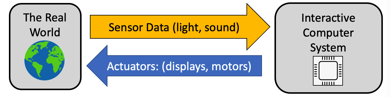
The sensors and actuators in this course span a wide range:
Sensors — buttons and switches, light sensors, distance sensors (ultrasonic and laser), sound sensors, motion and acceleration sensors, gesture sensors, compass, temperature, touch, voltage, and air-quality sensors.
Actuators — LEDs, DC motors, servo motors, stepper motors, character displays, graphic OLED displays, and color LCD screens.
Physical computing is powerful for teaching because students see results immediately. When you change one line of code, the LED blinks faster, the motor turns the other way, or the display shows something new.
What Is a Microcontroller?
A microcontroller is a tiny computer on a single chip. Unlike your laptop, a microcontroller has its processor, memory, and input/output connections all on one piece of silicon. It is designed to do one job reliably, often for years, without a screen or keyboard.
Microcontrollers are everywhere: in your microwave, your car's airbag system, your TV remote, and traffic lights. The ones we use in this course are inexpensive (under $10), programmable in Python, and powerful enough to control motors, read sensors, and connect to the internet.
The Raspberry Pi Pico Family
The Raspberry Pi Pico is the main microcontroller for this course. It is a small green board about the size of a stick of gum. It costs about $4 USD and is one of the most capable beginner microcontrollers available.
The Raspberry Pi Pico W adds a wireless module to the Pico. It can connect to Wi-Fi networks, making it an Internet of Things (IoT) device. The Pico W is the right choice for projects in Chapter 19 (Wireless and IoT).
At the heart of both boards is the RP2040 chip — a custom processor designed by Raspberry Pi Ltd. The RP2040 has:
- Dual ARM Cortex-M0+ cores running at up to 133 MHz
- 264 KB of RAM (temporary working memory)
- 2 MB of Flash memory (permanent storage for your programs, on the board)
- 26 usable GPIO pins
- 3 ADC channels (analog inputs)
- 8 Programmable I/O (PIO) state machines
The following table compares the key Pico specifications:
| Feature | Raspberry Pi Pico | Raspberry Pi Pico W |
|---|---|---|
| Price | ~$4 | ~$6 |
| Processor | RP2040 (dual-core 133 MHz) | RP2040 (dual-core 133 MHz) |
| RAM | 264 KB | 264 KB |
| Flash | 2 MB | 2 MB |
| Wi-Fi | No | Yes (2.4 GHz) |
| GPIO pins | 26 | 26 |
Other Compatible Boards
Several other boards are compatible with the code in this course:
- ESP32 / ESP8266 — WiFi-enabled microcontrollers from Espressif, popular for IoT projects, with more RAM than the Pico.
- Cytron Maker Pi RP2040 — a $11 educational board with the RP2040 chip, two motor channels, a buzzer, NeoPixels, and grove connectors built in. Perfect for robot projects.
- Maker Pi Pico / Maker Nano RP2040 — Cytron boards with different form factors but the same RP2040 chip.
- Micro:bit — a beginner board from the BBC, popular in schools, with a 5×5 LED matrix and Bluetooth.
- Raspberry Pi 500 Keyboard — a full keyboard with a Raspberry Pi computer inside, not a microcontroller, but useful as a host computer for Pico development.
GPIO Pins — The Pico's Interface to the World
GPIO stands for General-Purpose Input/Output. These pins are the Pico's connection to the physical world. You can configure each GPIO pin as either an input (to read a sensor or button) or an output (to control an LED or motor).
The Pico has 40 physical pins arranged around the board. Here is what you need to know about GPIO numbering:
- Pins are labeled GP0 through GP28 on the board (GP = General Purpose).
- The number in MicroPython matches the label:
Pin(0)controls GP0. - Not all physical pin positions match the GP number — always use the pinout diagram.
Pin modes (Input/Output) set whether a pin reads or writes:
1 2 3 4 | |
Diagram: Pico Pinout Explorer
Pico Pinout Explorer Interactive Diagram
Type: diagram
sim-id: pico-pinout-explorer
Library: p5.js
Status: Specified
Bloom Level: Remember (L1) Bloom Verb: identify Learning Objective: Students can identify the function of each pin on the Raspberry Pi Pico by name and number.
Canvas layout: - Center: a scaled top-down illustration of the Pico PCB (40 pin pads, two rows of 20) - Left and right margins: pin labels that align with the corresponding pad - Bottom: an info panel that shows pin details when a pad is hovered or clicked
Visual elements: - 40 pin pads color-coded by function: - Green: GPIO (GP0–GP28) - Red: 3.3V power - Black: Ground (GND) - Orange: ADC-capable pins (GP26–GP28) - Blue: I2C/SPI/UART pins - Yellow: VSYS, VBUS, RUN - Pin label next to each pad: e.g., "GP0 / SDA0 / UART0 TX"
Interactive controls: - Hover a pin pad: tooltip shows pin number, GPIO name, and alternate functions - Click a pin pad: info panel updates with full description, voltage, and a usage example - A legend in the corner explains the color coding - Filter buttons: "Show GPIO only", "Show Power only", "Show I2C pins"
Instructional Rationale: Color-coded interactive pinout with click-to-reveal lets students explore the Pico layout at their own pace, building spatial memory of pin locations.
Implementation: p5.js. Pin pads as small ellipses; color from function lookup; createButton() for filters; info panel as a rectangle with text.
Pull-Up and Pull-Down Resistors
When you configure a GPIO pin as an input, it needs to have a definite voltage — either HIGH (3.3 V) or LOW (0 V). An unconnected input pin is said to be floating — its value is unpredictable, like a coin spinning in the air.
A pull-up resistor connects the pin to 3.3 V through a high-value resistor. This makes the pin read HIGH when nothing is connected, and LOW when a button connects it to GND.
A pull-down resistor connects the pin to GND. This makes the pin read LOW when nothing is connected, and HIGH when a button connects it to 3.3 V.
The Pico has built-in pull-up and pull-down resistors that you activate in software:
1 2 | |
Key Idea: Pull-Ups Are the Default for Buttons
 Most button circuits use
 PULL_UP because it is simpler to wire — you connect one side of the button to the GPIO pin and the other side to GND. When the button is released, the pull-up holds the pin HIGH. When pressed, GND pulls it LOW. This "active LOW" pattern appears throughout physical computing.
Power: USB, VSYS, VBUS, and Ground
The Pico gets its power from the USB cable connected to your computer or a USB charger.
- USB Power — 5 V supplied through the USB connector.
- VBUS pin — directly connected to the USB 5 V supply. Use this to power 5 V components.
- VSYS pin — the main power input, which can also accept batteries (1.8–5.5 V). Always connected to the USB input through a diode.
- 3.3V pin — the regulated 3.3 V output from the Pico's onboard regulator. Used to power 3.3 V sensors and components.
- GND pins — Ground. Every component in your circuit must share a common GND with the Pico.
3.3 V vs 5 V Logic Levels
This is one of the most important concepts in physical computing. The Pico's GPIO pins operate at 3.3 V logic. That means:
- A HIGH output is 3.3 V.
- The maximum input voltage on a GPIO pin is 3.3 V.
Many older components (like the Arduino) operate at 5 V logic. Connecting a 5 V signal directly to a Pico GPIO pin can permanently damage the RP2040. Always check a component's datasheet before connecting it to the Pico.
Never Connect 5 V Signals to Pico GPIO Pins!
 Feeding 5 V into a 3.3 V GPIO pin will damage the RP2040 chip. If you need to connect a 5 V device, use a level shifter module to convert the voltage. When in doubt, measure with a multimeter before connecting.
Special RP2040 Features
Two features of the RP2040 deserve special attention because they unlock capabilities that other cheap microcontrollers cannot match.
RP2040 Dual Core — The RP2040 has two processor cores. Core 0 runs your main MicroPython program. Core 1 can run a second program at the same time. You will use this in Chapter 20 to blink an LED on Core 1 while Core 0 handles sensor reading.
RP2040 PIO (Programmable I/O) — The PIO subsystem contains eight tiny state machines that can handle precise timing signals in hardware — completely independently of the main cores. The PIO drives WS2812B NeoPixels flicker-free, implements custom communication protocols, and handles tasks that would overwhelm a software solution. You will see PIO in action in Chapter 22.
Flash Memory (2 MB on the Pico) stores your programs permanently. When you copy main.py to the Pico, it goes into flash memory and survives power cuts.
RAM (264 KB) is temporary working memory. Your running program, its variables, and its stack live in RAM. When you unplug the Pico, RAM is cleared.
Key Takeaways
- A microcontroller has processor, memory, and I/O on a single chip.
- The Raspberry Pi Pico uses the RP2040, costs ~$4, and has 26 GPIO pins.
- GPIO pins are configured as inputs or outputs in MicroPython using
Pin.OUT/Pin.IN. - Pull-up resistors hold a pin HIGH when nothing is connected; pull-down hold it LOW.
- Pico GPIO runs at 3.3 V — never connect a 5 V signal directly.
- VSYS accepts power from batteries; VBUS is the raw USB 5 V supply.
- The RP2040 has dual cores and PIO — advanced features you will use in later chapters.
Hardware Expert in Training!
 You now know your way around the Pico's hardware. You understand pins, power rails, logic levels, and the special capabilities of the RP2040. In Chapter 5 you will learn the electronics fundamentals — voltage, current, resistance, and Ohm's Law — that explain why circuits work the way they do. You're on a roll, maker!