Digital Input, Output, and Interrupts
Summary
This chapter is where your Python programs first interact with the physical world. You will learn to control LEDs by configuring GPIO pins as digital outputs, read button presses as digital inputs, and solve the real-world problem of contact bounce with both software and hardware debouncing techniques. The chapter also introduces interrupt service routines — a way to make your program instantly react to a button press or sensor event without constantly checking in a loop — using MicroPython's Pin.irq() method.
Concepts Covered
This chapter covers the following 18 concepts from the learning graph:
- Digital Output
- Digital Input
- HIGH and LOW States
- machine.Pin Class
- Pin.OUT Mode
- Pin.IN Mode
- Pin.value() Method
- LED Blink Program
- Button Input
- Button Debouncing
- Software Debouncing
- Hardware Debouncing
- Active High vs Active Low
- Internal LED
- External LED Circuit
- Interrupt Handler
- IRQ (Interrupt Request)
- Pin.irq() Method
Prerequisites
This chapter builds on concepts from:
Welcome to Chapter 6
 This is the chapter where your programs reach out and touch the real world. You will blink an LED from a Python command, read a button press, and — by the end of the chapter — have your Pico react to a button press instantly using interrupts. Grab your breadboard and let's go!
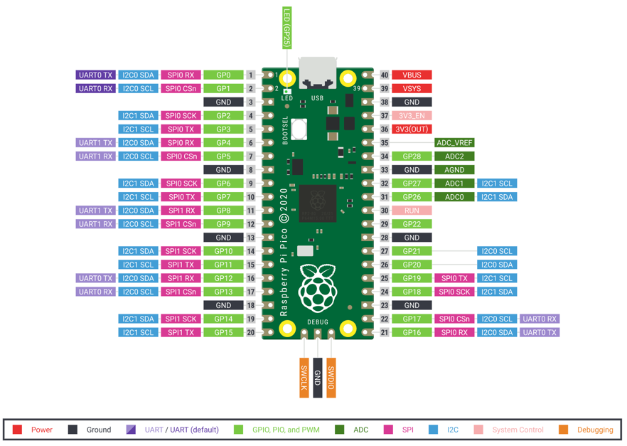
Pinout Diagram
Digital Signals: HIGH and LOW
In the physical world, a GPIO pin has exactly two possible states:
- HIGH — the pin is at or near 3.3 V. Think of it as "on."
- LOW — the pin is at or near 0 V (GND). Think of it as "off."
There are no in-between states in digital electronics. This is different from an analog signal (Chapter 7), which can take any value between 0 and 3.3 V. Every LED, button, switch, and logic chip you connect to the Pico communicates in this binary language of HIGH and LOW.
The machine.Pin Class
MicroPython controls GPIO pins through the machine.Pin class. It is the most-used class in all of physical computing with MicroPython. You always import it from the machine module.
1 | |
Creating a Pin object requires two things: the GPIO number and the direction mode.
Pin.OUT Mode — Digital Output
Pin.OUT mode tells the Pico to drive the pin to a specific voltage. Your program controls what comes out.
1 2 3 | |
Now led is a Python object that controls physical pin GP25.
Pin.IN Mode — Digital Input
Pin.IN mode tells the Pico to read the voltage that something else is applying to the pin.
1 | |
The third argument Pin.PULL_UP activates the internal pull-up resistor (see Chapter 4) so the pin reads HIGH when the button is not pressed and LOW when pressed.
Pin.value() Method
The Pin.value() method does two jobs depending on how you call it:
- With no argument: reads the current state of the pin (returns 0 or 1).
- With an argument: writes a new state to an output pin.
1 2 3 | |
You can also use led.toggle() to flip the output from HIGH to LOW or LOW to HIGH without knowing the current state.
Your First LED Blink Program
The LED blink program is the "Hello, World!" of hardware. Here it is in full:
1 2 3 4 5 6 7 8 9 10 11 | |
Each line:
- Pin(25, Pin.OUT) — creates the output object for GP25.
- led.value(1) — sets the pin HIGH, turning the LED on.
- utime.sleep(0.5) — pauses for half a second.
- led.value(0) — sets the pin LOW, turning the LED off.
- The while True: loop runs this forever.
Monty's Tip
 The onboard LED on GPIO 25 is the easiest LED to blink because it is already soldered to the board — no wires needed. Once you have the onboard LED blinking, add an external LED and resistor on a breadboard for extra practice.
Internal LED vs External LED Circuit
The internal LED (onboard LED) is built into the Pico board itself on GP25. It is always connected and ready to use — perfect for quick tests.
An external LED circuit uses a separate LED and a current-limiting resistor on a breadboard. To build a basic external LED circuit:
- Insert the LED anode (longer leg) into a row on the breadboard.
- Connect a 330 Ω resistor from that row to a GPIO pin (say, GP15).
- Connect the LED cathode (shorter leg) to GND.
1 2 | |
Reading a Button Press
Buttons are the simplest digital input. Wire a button between GP14 and GND. With Pin.PULL_UP, the pin reads:
- 1 (HIGH) — button not pressed (pull-up holds the pin HIGH)
- 0 (LOW) — button pressed (GND is connected to the pin)
This is called active LOW logic.
1 2 3 4 5 6 7 | |
Active High vs Active Low
Active High — the signal goes HIGH when the event occurs (e.g., a sensor that outputs 3.3 V when it detects motion). You use Pin.PULL_DOWN and check for value() == 1.
Active Low — the signal goes LOW when the event occurs (most buttons). You use Pin.PULL_UP and check for value() == 0.
The pull-up / pull-down setting and the check condition must match. Getting them backwards is a common beginner mistake.
Button Debouncing
Physical buttons are mechanical. When you press a button, the metal contacts bounce for a few milliseconds before settling. This causes the Pico to see dozens of rapid HIGH/LOW transitions in the time you intended just one press. This problem is called contact bounce or button noise.
Button debouncing is any technique that eliminates these spurious signals.
Software Debouncing
Software debouncing ignores changes that happen too close together. After detecting a press, you wait a short time (typically 20–50 ms) before checking again.
1 2 3 4 5 6 7 8 9 10 11 12 13 14 15 | |
Hardware Debouncing
Hardware debouncing uses a capacitor (typically 100 nF) wired from the button pin to GND. The capacitor absorbs the bounce energy and smooths the signal electrically, so the GPIO pin sees a clean edge. No extra code needed.
For most beginners, software debouncing is easier. Hardware debouncing is faster and requires no code, making it better for high-speed or interrupt-driven applications.
Diagram: Digital I/O Explorer
Digital I/O Explorer MicroSim
Type: microsim
sim-id: digital-io-explorer
Library: p5.js
Status: Specified
Bloom Level: Apply (L3) Bloom Verb: demonstrate Learning Objective: Students can trace the signal path from a button press through debouncing logic to an LED output, and predict the output state from a given input sequence.
Canvas layout: - Left column: animated button (click to toggle) with bounce waveform shown below it - Center: software debounce logic block with timer countdown - Right column: LED indicator showing the debounced output state
Visual elements: - Button click generates a noisy bouncing signal shown as a jittery waveform - A 30 ms timer bar in the center fills as the debounce delay runs - After the timer, the output LED changes state cleanly - Bounces that occur before the timer resets the timer
Interactive controls: - Click button: generates a simulated bounce (random count 3–8 bounces in 5 ms) - Slider: "Debounce time" (10–100 ms) - Toggle: "Software" vs "Hardware" mode (hardware shows a smoothed RC waveform instead of the bounce pattern)
Instructional Rationale: Seeing the bounce as an animation and watching the debounce timer absorb it makes the problem and solution vivid in a way that text alone cannot.
Implementation: p5.js. Use createSlider() for debounce time; button click starts a bounce animation (sinusoidal noise added to signal); debounce timer is a visual progress bar.
Interrupts — React Instantly Without Polling
The button-reading loop above uses polling — it checks button.value() on every loop cycle. This works, but the Pico is burning cycles checking the button even when nothing is happening. If the loop also controls a motor, plays a tune, or updates a display, a button press might be missed.
Interrupts solve this. An IRQ (Interrupt Request) is a hardware signal that immediately pauses the main program and runs a special function called an interrupt handler (or interrupt service routine). When the interrupt handler finishes, the main program resumes exactly where it stopped.
Pin.irq() Method
The Pin.irq() method registers an interrupt handler for a GPIO pin.
1 2 3 4 5 6 7 8 9 10 11 12 13 14 15 16 | |
Key arguments for Pin.irq():
| Argument | Meaning |
|---|---|
trigger=Pin.IRQ_FALLING |
Fire when pin goes HIGH → LOW (button pressed, active LOW) |
trigger=Pin.IRQ_RISING |
Fire when pin goes LOW → HIGH (button released) |
trigger=Pin.IRQ_FALLING \| Pin.IRQ_RISING |
Fire on both edges |
handler=my_function |
The function to call when the interrupt fires |
Keep Interrupt Handlers Short!
 Interrupt handlers must be fast. Do NOT call
 utime.sleep(), print to serial, or do heavy computation inside a handler. Instead, set a flag variable or increment a counter in the handler, then check that flag in the main loop. Long interrupt handlers can cause your program to behave unpredictably.
Putting It All Together
Here is a complete program that blinks an LED and counts button presses at the same time using an interrupt:
1 2 3 4 5 6 7 8 9 10 11 12 13 14 15 16 17 18 19 20 21 22 | |
This pattern — main loop doing steady work, interrupt handler reacting to events — is the foundation of almost every embedded program.
Key Takeaways
- GPIO pins are either HIGH (3.3 V) or LOW (0 V) — no in-between.
Pin(n, Pin.OUT)creates an output;Pin(n, Pin.IN, Pin.PULL_UP)creates an input with pull-up.pin.value(1)turns the output HIGH;pin.value(0)turns it LOW;pin.value()reads the input.- Buttons have contact bounce — use software (sleep + re-read) or hardware (capacitor) debouncing.
- Active LOW buttons read 0 when pressed; active HIGH read 1 when pressed.
Pin.irq()runs a handler function instantly when a pin changes, freeing the main loop for other work.- Keep interrupt handlers short — set flags, increment counters, then return.
Quick Check: Which trigger detects a button press on an active LOW circuit? (Click to reveal)
Pin.IRQ_FALLING — when the button connects the pin to GND, the pin voltage falls from HIGH (3.3 V) to LOW (0 V), triggering the FALLING interrupt.
You Control the Physical World!
 Congratulations — your Python program can now blink LEDs, read buttons, debounce contacts, and react instantly with interrupts. Chapter 7 takes this further into the analog world: reading varying voltages from potentiometers and sensors, and controlling motor speed with PWM signals. You are well on your way to building real projects!