Using a Motor Controller Board
Welcome to the Controller Board Lab
 Individual transistors and H-bridge chips work great for learning. But when you
want to build a real robot quickly, a motor controller board bundles everything
into one neat package. Let's build something amazing!
Individual transistors and H-bridge chips work great for learning. But when you
want to build a real robot quickly, a motor controller board bundles everything
into one neat package. Let's build something amazing!
What Is a Motor Controller Board?
A motor controller board is a small printed circuit that already has all the wiring built in. It connects your microcontroller to one or more motors with just a few wires — no loose transistors, no diodes, no messy breadboard circuits.
Most motor controller boards contain:
- An H-bridge chip (so each motor can go forward or backward)
- Screw terminals for the motor wires (so the connections stay tight)
- A power input for the motor battery
- Logic pins that plug into your Pico's GPIO pins
Key Idea
 The motor battery and the Pico's USB power are separate. Motors need their
own power supply — usually 4 × AA batteries — so they do not steal current
from your Pico.
The motor battery and the Pico's USB power are separate. Motors need their
own power supply — usually 4 × AA batteries — so they do not steal current
from your Pico.
The Maker Pi RP2040 Controller Board
One popular choice for MicroPython robots is the Maker Pi RP2040 from Cytron. It has a Raspberry Pi RP2040 chip built right in, along with:
- Two DC motor ports (M1 and M2) with screw terminals
- Four servo ports labelled SERVO1–SERVO4
- Two Grove connectors for plug-and-play sensors
- A piezo buzzer and two programmable RGB LEDs
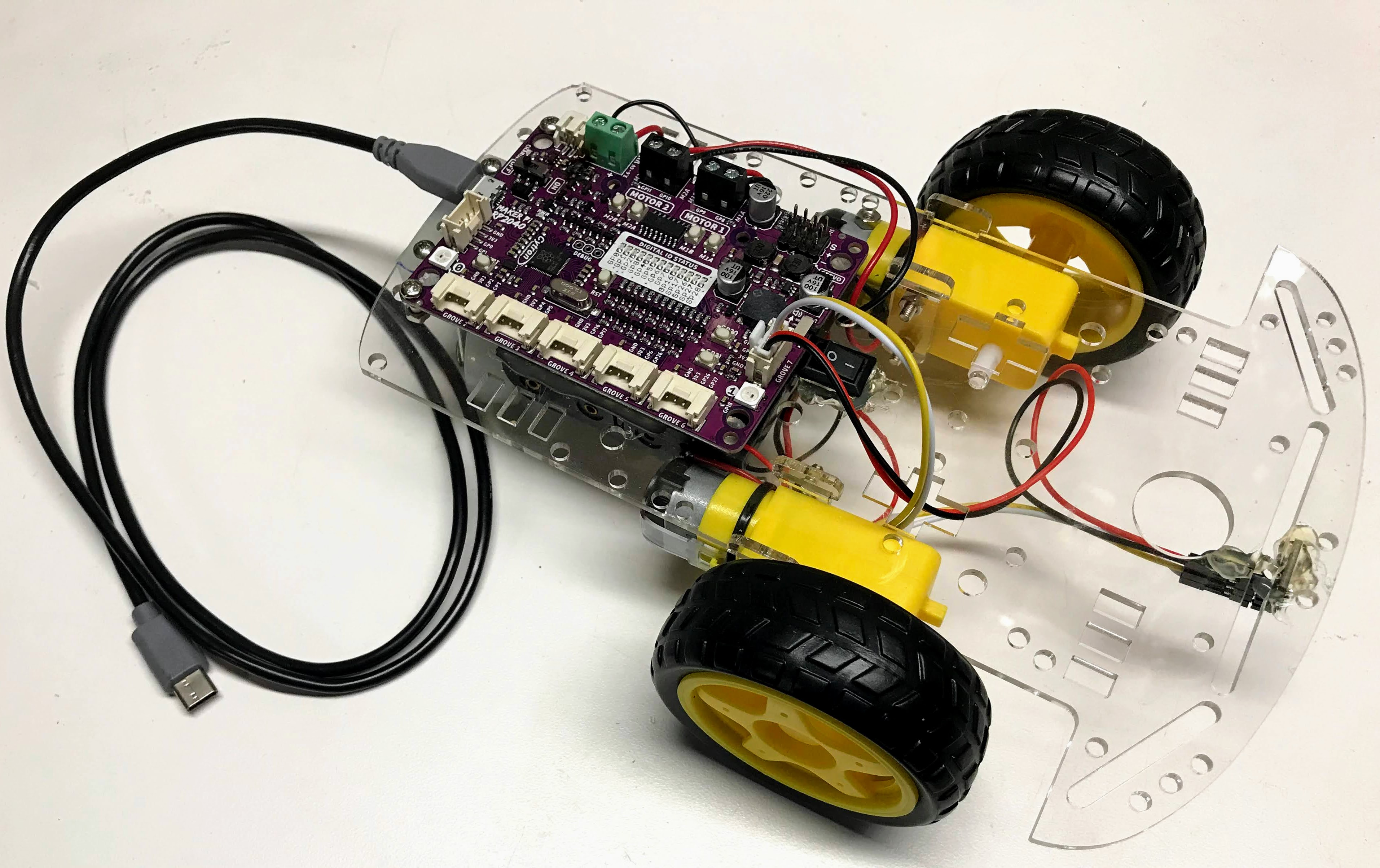
Because the RP2040 chip is already on the board, you do not need a separate Pico. You just plug in batteries, connect motors, and start coding.
Wiring a Two-Motor Robot
Follow these steps to connect two hobby DC motors to the M1 and M2 ports:
- Loosen the two screws on the M1 terminal.
- Insert the two wires from your left motor into M1 (one wire per hole).
- Tighten the screws firmly so the wires do not pull out.
- Repeat for the right motor on the M2 terminal.
- Connect your 4 × AA battery pack to the VIN and GND screw terminals.
- Plug the USB cable into the board to power the RP2040 logic.
Watch Out!
 Make sure the battery pack positive (red) wire goes to VIN and the
negative (black) wire goes to GND. Reversing them can damage the board.
Make sure the battery pack positive (red) wire goes to VIN and the
negative (black) wire goes to GND. Reversing them can damage the board.
Controlling the Motors in MicroPython
The Maker Pi RP2040 motor driver uses four GPIO pins — two per motor — to set direction and speed.
| Pin | Motor | Function |
|---|---|---|
| GP8 | M1 | Direction A |
| GP9 | M1 | Speed (PWM) |
| GP10 | M2 | Direction A |
| GP11 | M2 | Speed (PWM) |
Here is a simple program that drives both motors forward for two seconds, then stops:
1 2 3 4 5 6 7 8 9 10 11 12 13 14 15 16 17 18 19 20 21 22 23 24 25 26 27 28 29 | |
What Each Line Does
| Line | Purpose |
|---|---|
PWM(Pin(9)) |
Creates a PWM signal on the speed pin |
m1b.freq(1000) |
Sets the PWM frequency to 1 000 Hz |
m1a.value(1) |
Sets the direction pin HIGH (forward) |
m1b.duty_u16(49152) |
Sets speed to 75% (49 152 out of 65 535) |
m1b.duty_u16(0) |
Sets speed to 0% — motor stops |
Monty's Tip
 Try changing
 49152 to smaller numbers like 32768 (50%) or 16384 (25%)
to see how speed changes. PWM speed values range from 0 (stopped)
to 65535 (full speed).
Reversing a Motor
To reverse a motor, flip the direction pin from 1 to 0:
1 2 3 4 5 6 | |
Great Work!
 You can now control two motors with a real controller board — forward, backward,
and stopped. Next you will combine this with sensors so your robot can detect
obstacles and steer itself!
You can now control two motors with a real controller board — forward, backward,
and stopped. Next you will combine this with sensors so your robot can detect
obstacles and steer itself!