Introduction to Computational Thinking and Physical Computing
Hi — I'm Sparky, and I'll be with you all the way!
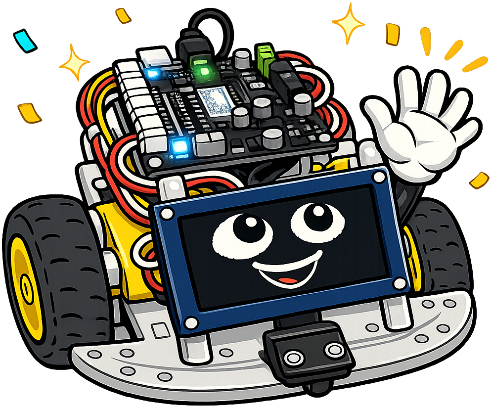 I'm Sparky — a cartoon version of the actual two-wheeled robot you will build in this course. I run on a Cytron Maker Pi RP2040 microcontroller, I have two big yellow wheels and an OLED display for a face, and I am genuinely excited to help you learn. I will pop into every chapter, but I do not show up randomly. I have exactly six jobs, and you will learn to recognize me by which one I am doing:
- Welcome you at the start of every chapter — that is what I am doing right now.
- Think with you when a concept is the kind that rewards slowing down and really picturing it.
- Give you a tip — the practical shortcut a working engineer would use but nobody writes down.
- Warn you about the exact spots where smart students trip up, so you can dodge the same pitfalls.
- Encourage you when a section is genuinely hard and it is completely okay to feel confused.
- Celebrate with you at the end of each chapter when you have earned it.
That's it. If I'm not doing one of those six things, I'm not in the chapter. Computational thinking is YOUR superpower — let's activate it!
Summary
This opening chapter establishes the intellectual foundation for the entire course. Students learn the four pillars of computational thinking — abstraction, algorithm design, decomposition, and pattern recognition — and discover how these ideas connect to building and programming physical robots. The chapter also introduces the engineering design process and basic electronics concepts (voltage, circuits, batteries) that underpin every subsequent hands-on lab.
Concepts Covered
This chapter covers the following 17 concepts from the learning graph:
- Computational Thinking
- Abstraction
- Algorithm Design
- Decomposition
- Pattern Recognition
- Problem Solving Strategy
- Debugging Fundamentals
- Testing and Iteration
- Physical Computing
- Experiential Learning
- Voltage and Current
- Basic Circuits
- Smart Car Chassis
- AA Batteries
- Engineering Design Process
- Build-Test-Improve Cycle
- Prototyping Methods
Prerequisites
This is the first chapter of the textbook. It assumes only the prerequisites listed in the course description: basic familiarity with a keyboard and web browser.
What Is Computational Thinking?
Imagine you need to get a robot from one side of a room to the other without hitting any walls. You can't just wave your hands and hope for the best. You need a plan. You need to think step by step. You need to predict what could go wrong.
That kind of careful, structured thinking has a name: computational thinking. Computational thinking is a way of solving problems that works everywhere — not just in robotics. Doctors use it to diagnose illness. Architects use it to design buildings. Scientists use it to study the natural world. And you are going to use it to make a robot move, sense its surroundings, and make decisions.
Computational thinking has four key pillars. Think of them as four mental tools you carry in your engineering toolbox. Let's look at each one using a simple challenge: How do we make a robot drive forward, stop before hitting a wall, and try again in a different direction?
Decomposition: Breaking Problems Apart
Decomposition means taking a big problem and cutting it into smaller, manageable pieces. Big problems feel overwhelming. Small problems feel solvable.
Our robot challenge seems huge at first: drive, detect walls, avoid them, keep going. But decomposition helps us split it into just three tasks:
- Make the motors spin forward.
- Read the distance sensor every tenth of a second.
- If the distance is too small, stop and turn.
Now each piece is something we can actually code. That is the power of decomposition.
Abstraction: Hiding What Doesn't Matter
Abstraction means focusing on what matters and ignoring details that don't. When you drive a car, you press the gas pedal — you do not think about how the fuel injectors work. The pedal is an abstraction that hides the engine's complexity from you.
In robot programming, we use abstraction constantly. Instead of thinking about exactly which electrical signals flow through which pins, we write motor_forward(speed=75). That one line hides dozens of low-level details. We focus on what the robot should do, not how the electricity makes it happen.
Pattern Recognition: Spotting What Repeats
Pattern recognition means finding structure that repeats — and using it so you don't reinvent the wheel. Once you know how to read one sensor, you can probably read any sensor. Once you know how to write one loop, you can write any loop.
Patterns show up everywhere in robotics. The sequence "read a sensor, make a decision, move a motor" appears in collision avoidance, line following, and light tracking. Spot the pattern once and you understand all three behaviors.
Algorithm Design: Writing the Steps
An algorithm is a precise set of steps that solves a problem. The word sounds intimidating, but you already know algorithms. A recipe is an algorithm. Directions to a friend's house are an algorithm. The steps to tie a shoelace are an algorithm.
In robotics, we write algorithms in MicroPython code. The collision avoidance algorithm might be: Check distance. If it's less than 20 centimeters, stop the motors, wait half a second, reverse for one second, turn randomly left or right, then drive forward again. Writing it precisely — so a computer can follow it without guessing — is algorithm design.
Before we continue, let's see how all four pillars work together as a team.
| Pillar | What It Means | Robot Example |
|---|---|---|
| Decomposition | Split big problems into small ones | Break "avoid walls" into: sense, decide, move |
| Abstraction | Hide details you don't need right now | Use motor_forward(speed) instead of pin-level code |
| Pattern Recognition | Find and reuse what repeats | The sense → decide → act loop appears in every behavior |
| Algorithm Design | Write the exact steps to solve the problem | Write the stop-reverse-turn sequence as runnable code |
Decomposition is easiest to learn by doing it. The tree below starts with one big goal, "Avoid the wall." You split it into smaller tasks, and then split those again, until each piece is small enough to write as a few lines of code.
Diagram: Robot Decomposition Tree
Run Robot Decomposition Tree Fullscreen
Split a big robot goal into smaller tasks until each one is simple enough to code
Type: microsim
sim-id: robot-decomposition-tree
Library: p5.js
Status: Specified
Reuse: moving-rainbow/decomposition-in-action (https://github.com/dmccreary/moving-rainbow/tree/main/docs/sims/decomposition-in-action). Replace the LED-strip goal with the robot goals below and add the "small enough to code" check.
Learning objective: Apply (Bloom L3) — break a robot goal into sub-tasks and decide when a task is small enough to write as code.
Canvas layout: 700 px wide (responsive), 520 px tall. Left 68%: the tree, with the goal at the top and children below. Right 32%: a "Goal Picker" panel and a status panel. Total iframe height 522 px.
Visual elements:
- Tree nodes are rounded rectangles with a label. Unsplit nodes are light blue (#bbdefb). Nodes marked "small enough" are green (#a5d6a7) with a small check mark. The selected node has an orange (#e65100) outline.
- Lines connect each parent to its children.
- A "pieces" counter in the status panel shows how many green (ready-to-code) leaf nodes exist, for example "3 of 3 pieces ready".
- A text bubble under each green node shows a one-line MicroPython idea, such as motor_forward(75).
Interactive controls: - Dropdown "Robot goal" with three choices: "Avoid the wall" (default), "Follow a line", "Show distance on the OLED". - Click any blue node, then click the "Split it" button. The node grows 2 to 3 children from a fixed answer bank for that goal. - "Small enough to code?" button, active when a node is selected. It marks a node green if it is a leaf in the answer bank, or shows the hint "Still too big. Can you split it more?" if not. - "Reset" button clears the tree back to the single goal node.
Behavior: - Answer bank for "Avoid the wall": Goal splits into (1) "Spin the motors forward", (2) "Read the distance sensor every 0.1 s", (3) "If distance is under 20 cm, stop and turn". Node 3 splits again into "Stop both motors", "Reverse for 1 s", "Turn left or right". All leaf nodes are "small enough". - Answer bank for "Follow a line": Goal splits into "Read the left and right line sensors", "Decide: is the line left, center, or right?", "Steer the motors to match". The middle node splits into "Left sensor sees dark", "Right sensor sees dark". - Answer bank for "Show distance on the OLED": Goal splits into "Read the distance sensor", "Turn the number into text", "Draw the text on the OLED". - A node marked "small enough" cannot be split again. Splitting a green node shows "Already small. Time to code it!" - When every leaf is green, the status panel shows "Fully decomposed! Each piece is ready to code." and the tree glows softly.
Default state: "Avoid the wall" selected, only the goal node shown, no node selected, counter reads "0 pieces ready".
Assessment/Challenge: Fully decompose "Avoid the wall". How many green pieces do you end up with? (Answer: 5.) Then say which pillar you just used. (Answer: decomposition.)
Responsive: redraw on window resize. On narrow screens the right panel stacks below the tree.
Notice how each green piece is small enough to test on its own. That is what makes robot code easier to write and debug. In the labs, you will write each piece as its own function, such as one function for reading the sensor and one for turning.
Hmm, think about this for a second…
 Next time you do something in daily life — making breakfast, finding your way around school, packing a bag — try to catch yourself using one of the four pillars. You will be surprised how often your brain already thinks computationally. We're just giving those habits names so we can use them on purpose.
Problem Solving and Debugging
Knowing the four pillars is great. Applying them to a real problem is where learning actually happens. In this course, you will run into problems every single day. Wires will be loose. Code will have typos. The robot will spin when you told it to go straight. That is not failure — that is engineering.
A Strategy for Hard Problems
Problem solving is the skill of working through a challenge systematically, even when you don't know the answer yet. When you get stuck, it helps to have a plan. Here is a simple strategy used by engineers at every level:
- Understand the problem. What exactly is supposed to happen? What is actually happening instead?
- Break it into pieces. Which part is failing — the hardware, the code, or a specific line?
- Form a hypothesis. Make a guess: "I think the problem is the motor speed value."
- Test one thing at a time. Change only one thing, then check whether it fixed the problem.
- Learn from the result. Whether it worked or not, you now know something you didn't before.
This strategy is a form of the scientific method. It works just as well in a robotics lab as it does in a chemistry lab.
Debugging: What to Do When Things Break
Debugging is the process of finding and fixing errors in code. The word "bug" has been part of programming since the 1940s, when an actual moth got stuck in a computer relay and caused it to malfunction. Today, a "bug" is any error that causes code to behave unexpectedly.
Bugs fall into two main categories. A syntax error is a typo or grammar mistake — like a missing colon or a misspelled keyword. Python catches these before your code even runs. A logic error is harder to spot: your code runs without crashing, but it does the wrong thing. Logic errors are exactly what the problem-solving strategy above is designed to find.
Before you use the debugging checklist below, here is one mindset shift that will save you hours: every error message is useful information. It is the computer telling you where to look. Never delete your code in frustration. Read the error, narrow it down, and change one thing at a time.
| Debugging Step | Question to Ask | What to Do |
|---|---|---|
| Read the error | What does the error say, exactly? | Read it word by word — don't just skim |
| Find the line | Which line caused the error? | Go to that line in Thonny |
| Check the obvious | Any typos, wrong indentation, missing colons? | Compare to a working example |
| Add a print statement | What is the value of each variable? | Print variables at key points to trace the problem |
| Undo the last change | Did the code work before your last edit? | Revert that one change and test again |
A checklist is helpful, but real bugs come with real symptoms. The flowchart below lets you pick a robot problem and follow the questions an engineer would ask, one step at a time.
Diagram: Robot Debugging Flowchart
Run Robot Debugging Flowchart Fullscreen
Walk through yes/no debugging questions for common robot symptoms
Type: microsim
sim-id: robot-debugging-flowchart
Library: p5.js
Status: Specified
Reuse: computer-science/debugging-flowchart (https://github.com/dmccreary/computer-science/tree/main/docs/sims/debugging-flowchart). Replace the generic software questions with the robot symptoms and questions below.
Learning objective: Apply (Bloom L3) — use a step-by-step debugging path to decide whether a robot problem comes from hardware or code, and to choose one thing to change.
Canvas layout: 700 px wide (responsive), 540 px tall. Top strip (60 px): symptom dropdown and Restart button. Main area: a vertical flowchart of diamonds (questions) and rectangles (actions). Bottom strip (60 px): a "What I have learned" log. Total iframe height 542 px.
Visual elements: - Question nodes are yellow diamonds (#fff59d). Action nodes are light blue rectangles (#bbdefb). Final "fix" nodes are green (#a5d6a7). - The current node has an orange (#e65100) outline and pulses gently. Nodes already visited turn gray with a small check. - The flow line from visited nodes to the current node is drawn thick navy (#1a237e). - The log strip lists each answer as text, for example "Error message read: yes".
Interactive controls: - Dropdown "Symptom": "Nothing happens when I power on" (default), "Error message in Thonny", "Robot spins instead of going straight", "Robot runs but does the wrong thing". - "Yes" and "No" buttons under the current question node. - "Restart" button returns to the first question for the selected symptom.
Behavior: - Each symptom has its own path of 4 to 6 nodes. Example for "Robot spins instead of going straight": Q1 "Did it work before your last change?" Yes leads to action "Undo the last change and test again". No leads to Q2 "Are both motor wires firmly in M1 and M2?" No leads to fix "Reseat the wires, tighten screws". Yes leads to Q3 "Are both motors given the same speed in code?" No leads to fix "Set both speeds to the same value". Yes leads to action "Add a print statement for each speed". - Example for "Error message in Thonny": Q1 "Did you read the error word by word?" No leads to action "Read it now". Yes leads to Q2 "Does it say SyntaxError?" Yes leads to fix "Check colons, quotes, and indentation on the named line". No leads to fix "It is a logic or name error. Print your variables." - Example for "Nothing happens": Q1 "Is the green power LED on?" then Q2 "Are the batteries fresh?" then Q3 "Was the program saved as main.py on the board?" - Every path ends in exactly one green fix node and a Sparky-style message: "Change only that one thing, then test again." - The log records every answer so the student can see their own reasoning trail.
Default state: symptom "Nothing happens when I power on", first question shown, log empty.
Assessment/Challenge: Choose "Robot spins instead of going straight" and answer No, No, Yes. What is the last action node? (Answer: "Add a print statement for each speed".) Which debugging table step is that? (Answer: "Add a print statement".)
Responsive: redraw on window resize. Diamonds shrink but keep a minimum 44 px tap target for the Yes and No buttons.
Debugging is a skill, not luck. Each question in the flowchart matches a step from the table above, and each path ends with one small change you can test on your robot. Trying the flowchart on a real bug in your first lab will feel much less scary.
Testing and Iteration: Improve Every Time
Testing means deliberately checking whether your code does what you intended. Iteration means taking what you learned from testing and improving the code. Together, testing and iteration form a loop: build → test → improve → repeat.
The best engineers do not write perfect code on the first try. Nobody does. They write code, test it, find something to improve, fix it, and test again. Each pass through the loop makes the robot a little better.
Here's a trick that saves me a lot of trouble…
 When testing your robot, change only one thing at a time. Under pressure it's tempting to fix three things at once. But if you do that and the robot suddenly works, you won't know which fix actually helped — or which of the other changes might cause problems later.
Physical Computing: Where Code Meets the World
Most computer programs live entirely inside a machine. You type text, click buttons, and see results on a screen. Everything stays digital. Physical computing is different — it connects a program to the real, physical world through sensors and motors.
Your robot is a physical computing device. When it reads a distance measurement from its sensor, it converts a physical gap into a number your code can use. When it spins its motors based on that number, it turns a digital decision into a physical action. Code becomes movement.
Inputs: The Robot's Senses
An input is any information flowing from the real world into the robot's computer. Your robot has several inputs:
- The time-of-flight distance sensor measures how far away the nearest object is.
- Infrared line sensors detect a dark line on a light surface.
- A bump sensor detects physical contact with an obstacle.
Every input converts something physical — light, distance, touch — into a number the microcontroller can read.
Outputs: How the Robot Acts
An output is any action the robot takes in the physical world. Your robot's outputs include:
- DC motors that spin the wheels forward or backward.
- NeoPixel LEDs that display any color.
- The piezo buzzer that plays tones.
- The OLED display that shows text and graphics.
The robot's microcontroller constantly reads inputs, runs your code, and triggers outputs. That loop — sense, decide, act — is the heartbeat of every robot program you will write.
The diagram below shows how these three layers fit together. Click any component to learn what it does in the physical computing system.
Diagram: Physical Computing Explorer
Run Physical Computing Explorer Fullscreen
Interactive diagram showing inputs, the microcontroller, and outputs forming the sense-decide-act loop
Type: MicroSim
sim-id: physical-computing-explorer
Library: p5.js
Status: Specified
Learning objective: Students will identify (Bloom L1: Remember) the three layers of a physical computing system — inputs, processor, and outputs — and explain (Bloom L2: Understand) how information flows through the sense → decide → act loop.
Canvas size: 700 × 380 px, responsive (fills container width on resize)
Layout: Three vertical columns separated by animated flowing arrows:
Left column — Inputs: Three sensor icons stacked vertically with labels: "Distance Sensor (ToF)", "Line Sensors (IR)", "Bump Sensor". Each icon is drawn as a simple geometric shape with a colored border. All three connect via dashed animated lines flowing rightward.
Center column — Processor: A rounded rectangle labeled "Cytron Maker Pi RP2040" with "MicroPython Code" in smaller text inside and a blinking cursor. Color: navy (#1a237e). Animated dashed lines flow in from the left and out to the right.
Right column — Outputs: Three output icons with labels: "DC Motors", "NeoPixel LEDs", "OLED Display". Each icon uses the appropriate visual metaphor (spinning wheel, colored dot grid, small screen).
Interactions:
- Clicking any input icon highlights it yellow (#f9a825) and opens a tooltip popup stating: the sensor name, what physical phenomenon it measures, and an example reading (e.g., "Time-of-flight sensor: measures reflected infrared light. Example: 24 cm to nearest obstacle.").
- Clicking the center processor box shows: "The microcontroller reads every input, executes your MicroPython code, and decides what outputs to trigger — all in milliseconds."
- Clicking any output icon shows: the output name, what physical action it produces, and an example value (e.g., "DC Motors: spin the wheels. Example: speed=75 means 75% of full power.").
- A "Play Loop" button (bottom-center, created with p5's createButton()) starts an animation where orange (#e65100) particles travel along the wire paths from left to right, illustrating the sense → decide → act cycle in motion. Clicking again pauses the animation.
Visual style: Bold flat illustration, thick black outlines, transparent background. Tooltips appear as navy (#1a237e) rounded rectangles with white text, positioned adjacent to the clicked element.
Implementation: p5.js sketch with icons drawn programmatically using rect(), ellipse(), and line(). Tooltip divs managed as HTML elements parented to the canvas container. createButton() for the Play Loop control. Canvas resizes by calling resizeCanvas(windowWidth * 0.9, 380) in windowResized().
Learning by Building
Experiential learning means learning by doing, not just by reading. In this course, you will not just hear about PWM motor control — you will write the code, run it on your robot, and watch the wheels spin. You will not just read about debugging — you will debug real errors in real code and feel genuinely satisfied when they are fixed.
The concepts in this textbook are the same ones found in university robotics courses. But you will understand them deeply because you will feel them happen on the hardware in your hands.
This part is tricky. That's okay. You're doing it anyway.
 The connection between code and physical hardware is the hardest mental leap in this whole course. A number in your code actually makes a motor spin. A spinning motor actually moves a wheel. It feels magical at first. Give yourself permission to find it confusing — it will click, I promise. Every maker goes through this exact moment.
Electronics Basics
Before you start wiring your robot, you need a mental model of how electricity works. You do not need an electronics degree. But three ideas will unlock everything else: voltage, current, and circuits.
Voltage and Current
Imagine a water tower sitting on a hill. The height of the water creates pressure that pushes water through pipes. Voltage is like that pressure — it is the force that pushes electric charge through a wire. We measure voltage in volts (V).
Now imagine the amount of water actually flowing through the pipe. Current is the amount of electric charge flowing per second. We measure current in amperes, or amps (A). More voltage means more push. More current means more charge flowing.
Your robot gets its voltage from AA batteries. Each AA battery provides 1.5 volts. Four batteries connected end to end — called a series connection — give you 6 volts total. That 6 volts powers your microcontroller, your motors, and your sensors.
Water is a good picture for voltage and current, but it is easier to feel when you can turn the knobs yourself. In the simulation below, a pump pushes water around a loop of pipe. A battery pushes charge around a loop of wire in the same way.
Diagram: Voltage and Current Water Analogy
Run Voltage and Current Water Analogy Fullscreen
Side-by-side water pipe loop and electric circuit that respond to the same voltage and resistance sliders
Type: microsim
sim-id: voltage-current-water-analogy
Library: p5.js
Status: Specified
Reuse: circuits/water-flow-analogy (https://github.com/dmccreary/circuits/tree/main/docs/sims/water-flow-analogy) and learning-micropython/ohms-law-calculator (https://github.com/dmccreary/learning-micropython/tree/main/docs/sims/ohms-law-calculator). Keep the two-panel analogy; use the calculator's current readout and set the load to a robot motor.
Learning objective: Explain (Bloom L2) — describe how voltage acts like water pressure and current acts like water flow, and predict what happens when either one changes.
Canvas layout: 700 px wide (responsive), 420 px tall. Left half: "Water Loop". Right half: "Robot Circuit". Bottom strip (90 px): two sliders and a readout row. Total iframe height 422 px.
Visual elements: - Left panel: a rectangular pipe loop with a pump on the left side (labeled "Pump = Battery"), a narrow section on the right (labeled "Narrow pipe = Motor"), and blue dots that flow around the loop. Dot speed shows flow. - Right panel: the same loop drawn as wire, with a battery symbol on the left (labeled "Battery pack") and a motor circle with "M" on the right. Yellow dots (charge) flow around the wire at the same speed as the blue dots. - A pressure gauge under the pump and a voltage label under the battery show matching values. - The wire and pipe colors: pipe steel blue (#1976d2), wire navy (#1a237e), motor circle orange (#e65100). - If the loop is broken (see the switch below), the dots stop and a red "Open circuit: no flow" banner appears.
Interactive controls: - Slider "Voltage (batteries in series)": 1 to 4 batteries, step 1, default 4. Each battery adds 1.5 V, so the label shows "6.0 V" at 4. - Slider "Motor resistance (load)": 5 to 30 ohms, step 1, default 12. - Toggle button "Break the loop" that opens the circuit; it becomes "Fix the loop" when open. - Readout row: "Voltage = X V", "Resistance = Y ohms", "Current = Z A".
Behavior: - Current = Voltage / Resistance. At the defaults, 6.0 V / 12 ohms = 0.50 A. - Dot speed on both sides is proportional to current, from stopped at 0 A to a maximum at 1.2 A (6.0 V across 5 ohms). - Pump pressure gauge height is proportional to voltage. - The pipe gets visibly narrower as resistance goes up. - Open loop sets current to 0 A and stops all dots. Closing the loop restores the flow. - Formula text under the sliders shows the math, for example "6.0 V / 12 ohms = 0.50 A".
Default state: 4 batteries, 12 ohms, loop closed, dots flowing at medium speed.
Assessment/Challenge: Set the sliders so the current is exactly 0.30 A. (Answer: 3 batteries at 4.5 V with 15 ohms gives 0.30 A. 2 batteries at 3.0 V with 10 ohms also works.) Then explain in one sentence why the dots stop when you break the loop.
Responsive: redraw on window resize. On narrow screens the two panels stack, water on top.
Your robot is the same idea in a smaller package. The battery pack is the pump, the wires are the pipes, and the motors are the narrow section that does the work. When the loop breaks, or the batteries push too weakly, the robot slows or stops.
Basic Circuits
A circuit is a complete loop for electricity to travel through. Electricity needs a continuous path from the positive terminal of a power source, through the components, and back to the negative terminal. If the path breaks anywhere — a loose wire, a disconnected plug — no current flows and nothing works.
Think of a circuit like a circular racetrack. The electrons can only keep moving if the track is a complete loop. Break the track anywhere and every car stops. In your robot, every component — the microcontroller, the motors, the sensors, the LEDs — is part of the circuit. When you wire the robot, you are building that racetrack carefully, making sure every connection is solid.
Heads up — this one tripped me up the first time too.
 Always remove the batteries before changing any wires. Connecting or disconnecting wires while the power is on can cause a short circuit — electricity takes a shortcut that bypasses your components. Short circuits can damage the microcontroller board and drain your batteries in seconds. Power off first, wire second, power on last. Every time.
Your Battery Pack
AA batteries are small, cylindrical cells that store chemical energy and convert it to electrical energy. Your battery holder holds four AA alkaline batteries — the standard type found at any grocery store. Four batteries in series gives you 6 volts total to power the entire robot.
When your robot starts acting sluggish or the code behaves strangely, check your batteries first. A nearly-dead battery delivers less voltage than it should. Less voltage means motors spin slower, sensors read incorrectly, and the microcontroller may crash or reset unexpectedly. Fresh batteries fix a surprising number of "mysterious" problems.
You can see this for yourself in the simulation below. It lets you wear down the batteries and watch the robot get slower, then start acting strangely.
Diagram: Battery Pack Health Explorer
Run Battery Pack Health Explorer Fullscreen
Four AA batteries in series, with a charge slider that shows how weak batteries change motor speed and reset risk
Type: microsim
sim-id: battery-pack-health-explorer
Library: p5.js
Status: Specified
Reuse: intro-to-physics-course/series-parallel (https://github.com/dmccreary/intro-to-physics-course/tree/main/docs/sims/series-parallel). Keep the series battery drawing; remove the parallel option and add the robot health readouts below.
Learning objective: Analyze (Bloom L4) — connect the voltage of a four-battery pack to motor speed and to the risk that the microcontroller resets.
Canvas layout: 700 px wide (responsive), 440 px tall. Top 55%: the battery pack drawing and a robot top view. Bottom 45%: control strip and readouts. Total iframe height 442 px.
Visual elements: - Four AA battery shapes in a row, connected end to end (+ to -), each labeled with its own voltage, for example "1.5 V". Battery fill color runs from green (#43a047) at full charge to yellow (#fdd835) to red (#e53935) when weak. - A total voltage bar: horizontal, 0 to 6 V, with a green zone from 4.8 to 6 V, a yellow zone from 4.0 to 4.8 V, and a red zone below 4.0 V. - A small top-view robot with two wheels. Wheel spin animation speed matches the motor speed. - A status lamp labeled "Brain (RP2040)": green when OK, blinking red when "Reset risk". - A text bubble from Sparky: "Fresh batteries!", "Getting sluggish...", or "Try new batteries!"
Interactive controls: - Slider "Battery charge": 100% down to 0%, step 5%, default 100%. - Radio buttons "Program command": "Full speed (duty 65535)" (default) and "Half speed (duty 32768)". - Button "Swap in fresh batteries" sets charge back to 100%. - Toggle "Wear down over time" starts a slow auto-drain of 1% per second until the student turns it off or reaches 0%.
Behavior: - Each battery voltage = 0.9 + 0.6 x (charge / 100) volts. At 100% each is 1.5 V (total 6.0 V). At 0% each is 0.9 V (total 3.6 V). - Pack voltage = 4 x per-battery voltage. - Motor speed shown = (pack voltage / 6.0) x commanded duty. At 100% charge and full duty this reads 100% speed. At 50% charge the pack is 4.8 V, so full duty gives 80% speed. - Status lamp: green when pack voltage is 4.5 V or higher; blinking red when below 4.5 V, with the message "The board may reset or read sensors wrong." - Readouts: "Pack voltage", "Motor speed (% of best)", "Board status". - Half speed always shows half of whatever the full-speed value is.
Default state: 100% charge, full speed, all batteries green, lamp green, "6.0 V", "100%".
Assessment/Challenge: Find the highest charge percent at which the board first shows "Reset risk". (Answer: 35%. The lamp turns red below 4.5 V, which happens at a charge of 37.5%, and the slider moves in 5% steps, so 40% is still green and 35% is red.) Then say what you would check first if your real robot drives slowly.
Responsive: redraw on window resize. On narrow screens the robot view moves below the battery row.
The values in this simulation are simplified, but the lesson is real. Weak batteries lower the voltage, and lower voltage means slower motors and strange behavior. Before you blame your code, put in a fresh pack.
Meet Your Robot: The Smart Car Chassis
The Smart Car Chassis is the physical platform your robot is built on. It is a flat acrylic plate with mounting holes for motors, wheels, and a battery holder. The chassis gives your robot its structure — like a skeleton that everything else attaches to.
Your robot is powered by the Cytron Maker Pi RP2040 board — a microcontroller designed specifically for controlling hardware. It has two DC motor drivers built in, a USB port for programming, and connectors for sensors and servos. It runs MicroPython, which means you program it in Python — one of the world's most popular and beginner-friendly programming languages.
Here is a map of the key components you will use throughout this course:
| Component | What It Does |
|---|---|
| Cytron Maker Pi RP2040 | The brain — runs MicroPython code and controls all hardware |
| DC Motors (×2) | Spin the wheels forward or backward |
| Yellow Wheels (×2) | Roll the robot across the floor |
| Time-of-Flight Sensor | Measures distance to the nearest obstacle in centimeters |
| NeoPixel LEDs (×2) | Display any color — great for status and debugging |
| Piezo Buzzer | Plays tones and beeps |
| Battery Holder | Holds four AA batteries (6 V total) |
The Engineering Design Process
Engineers do not sit down and write a perfect plan before they begin. They start with a rough idea, build something quick, test it, see what breaks, and improve it. This structured cycle for turning ideas into working things is called the engineering design process.
Build, Test, Improve
The engineering design process has three core phases, and they repeat in a cycle:
- Build — create a prototype (a quick, working version) of your idea.
- Test — run the prototype and observe what happens. Does it do what you intended?
- Improve — based on what you learned from testing, change one thing and build again.
This build-test-improve cycle is exactly what you will follow in every lab. You will never be asked to write a perfect program from scratch. You will always start from a working example, test it on your actual robot, and add one feature at a time.
The diagram below shows how the three phases connect. Click any phase to read what it involves.
1 2 3 4 5 6 7 | |
Prototyping Methods
A prototype is an early, rough version of something — built quickly to test an idea. In robotics, prototypes come in several forms:
- Code prototypes — a short program that tests one single behavior, such as spinning only the left motor.
- Hardware prototypes — a quick physical assembly that checks whether components connect and fit correctly.
- Paper prototypes — a sketch or diagram of an algorithm on paper before writing any code, to make sure the logic makes sense first.
In this course, you will use all three. Good engineers are not attached to their first prototype. They expect it to change. The goal of a prototype is to learn something — and then use that learning to build a better version.
Double thumbs-up! You just built the foundation for everything!
 You covered a lot of ground in this chapter. You know the four pillars of computational thinking. You have a strategy for tackling hard problems and debugging broken code. You understand how physical computing connects code to the real world. You know how voltage and circuits work well enough to wire your robot safely. And you have a clear picture of every component on the Smart Car Chassis. That is the complete foundation. You now think like an engineer.