Breadboard Wiring and Electrical Fundamentals
Summary
This chapter builds the electrical foundation every Pico project in the book depends on: how a breadboard's rails and rows connect components, how GPIO pins are numbered and addressed, and the core quantities -- voltage, current, and resistance -- related by Ohm's Law. It introduces resistors (including pull-up and pull-down configurations), capacitors, and the basic LED circuit: polarity, forward voltage, and the current-limiting resistor that protects an LED from burning out. Students finishing this chapter will be able to wire a simple LED circuit on a breadboard correctly and explain why a current-limiting resistor is required.
Concepts Covered
This chapter covers the following 22 concepts from the learning graph:
- Breadboard
- Breadboard Rail
- Breadboard Row
- Jumper Wire
- GPIO Pin
- Pin Numbering
- Digital Pin
- Analog Pin
- Voltage
- Current
- Resistance
- Ohms Law
- Resistor
- Pull Up Resistor
- Pull Down Resistor
- Capacitor
- LED
- LED Polarity
- Forward Voltage
- Current Limiting Resistor
- Ground
- VCC
Prerequisites
This chapter builds on concepts from:
Time to Get Your Hands Dirty
 You picked your board in Chapter 2 — now let's plug something into it. This chapter is where the abstract idea of "circuit" becomes a real board full of wires you can touch, test, and (occasionally) get wrong on purpose so you learn why it matters. Let's build something!
Every physical project in this book starts on the same piece of hardware: a small plastic board full of tiny holes that lets you connect components without soldering a single joint. This chapter builds the electrical foundation everything else rests on — how that board is wired internally, how your Pico's pins are numbered, and the handful of physics concepts (voltage, current, resistance) that explain why a circuit works, or why it doesn't.
The Breadboard: A Reusable Circuit Canvas
A breadboard is a rectangular plastic board full of small spring-loaded holes that let you build and rewire electronic circuits without soldering, simply by pushing component legs and wires into the holes. What makes a breadboard useful isn't the holes themselves — it's the hidden metal strips underneath them that connect certain holes together electrically, so plugging two components into the same connected group joins them into the same circuit.
Those hidden strips come in two different patterns, and knowing the difference is the single most important skill in this chapter. A breadboard row is a short strip of five connected holes running across the middle section of the board, typically labeled with a letter (A through E, or F through J) and a number — any two components plugged into the same row are automatically connected to each other. A breadboard rail is a long strip of connected holes running the full length of the board along its top and bottom edges, usually marked with a red line (power) and a blue or black line (ground), used to distribute power to many components at once without running a separate wire from the microcontroller to each one.
Berry's Key Insight
 Rows run sideways in short five-hole groups; rails run the full length of the board. That's the whole trick. Every wiring mistake I see from new makers traces back to forgetting that a row is only five holes long — plug two components three columns apart and they are not connected at all.
Components don't move themselves from one hole to another, so every breadboard circuit needs a way to physically bridge two points. A jumper wire is a short, flexible wire with a solid pin on each end, used to connect a breadboard hole to another hole, to a rail, or directly to a pin on the Pico. Jumper wires come in different lengths and sometimes different colors, and while color has no electrical meaning to the breadboard itself, using a consistent color scheme (red for power, black for ground) makes a circuit far easier to read and debug later.
Before we look at an interactive breadboard, let's connect two more terms you'll need: ground and VCC. Ground is the common reference point in a circuit that current returns to, treated as the "zero volts" baseline every other voltage in the circuit is measured against — on a breadboard, it's almost always the rail marked with a black or blue line. VCC is the label for the positive supply voltage rail in a circuit, short for "voltage at the common collector" historically, though today it's simply understood to mean "the positive power connection." Every working circuit needs a path from VCC, through your components, back to ground — break that path anywhere and nothing will work.
Now that rails, rows, jumper wires, ground, and VCC are all defined, let's explore how they fit together on a real board.
Diagram: Breadboard Anatomy Explorer
Run the Breadboard Anatomy Explorer MicroSim fullscreen
Breadboard Anatomy Explorer (interactive diagram)
Type: interactive-diagram
sim-id: breadboard-anatomy-explorer
Library: p5.js
Template: https://github.com/dmccreary/stem-robots/tree/main/docs/sims/breadboard-layout-explorer
Status: Specified
Learning objective: Students will identify (Bloom L1: Remember) which holes on a breadboard are electrically connected, and trace (Bloom L2: Understand) a circuit path from a power rail through a component to ground.
Canvas: 700x420px default, responsive — recompute hole spacing as a fraction of windowWidth inside windowResized() so the full breadboard stays visible without horizontal scrolling down to 360px wide.
Layout: a top-down illustration of a half-size breadboard: two power rails along the top (red VCC line, blue ground line) and two along the bottom, with a central gap separating two five-row, many-column terminal strip sections drawn as a grid of small circles.
Interaction: clicking any single hole highlights every other hole electrically connected to it in raspberry #C2185B, and shows a small label ("Row E, columns 12-16" or "Bottom ground rail") in an infobox beneath the diagram. A createButton() labeled "Place Jumper Wire" lets a student click two holes in sequence to draw a wire between them and see immediately whether the two holes were already connected (wire turns green) or genuinely bridges two separate groups (wire turns gold). A "Clear Wires" button resets all placed wires.
Implementation: p5.js. Store the breadboard's internal connectivity as a lookup table mapping each hole's (row, column) position to a connection-group ID; clicking a hole highlights every hole sharing its group ID. Draw holes with ellipse() in a nested loop over rows and columns, and jumper wires as bezier() curves connecting two hole centers. Recalculate all hole coordinates from canvas width inside windowResized().
Pico on the Breadboard
Many of the Raspberry Pi Pico projects in this book and the eight related intelligent textbooks use the low-cost ($4) Raspberry Pi Pico on a breadboard.
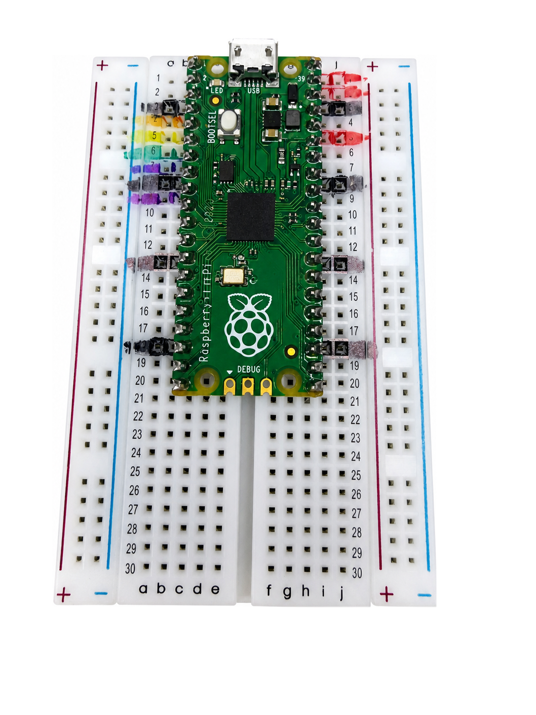
The image above is a photograph of the Raspberry Pi Pico mounted on a half-size solderless breadboard. This is known as a 400-tie point breadboard since there are around 400 holes in the breadboard that you could make a connection.
One challenge with the Raspberry Pi Pico is that most of the pins are not labeled on the top of the board. So when a student wants to make a connection, they have to be careful to look at the diagrams and count the number of rows down from the top to get the right connection. To help students make the right connection we have used colored markers to mark some of the common connections. Here is the pattern:
- All the ground pins on both sides are black. These are all rows that end with the numbers "3" and "8": 3, 8, 13 and 18.
- The pins on the right related to power are red (VBUS, VSYS, 3.3V OUT)
- The rows on the left side have colors that can be matched to a ribbon cable. Row 4 is orange, row 5 is yellow, row 6 is green, row 7 is blue and after skipping row 8 (gnd) row 9 is purple.
Talking to the Pico: GPIO Pins
A breadboard only becomes useful once it's connected to a microcontroller, and the Pico connects through a row of metal legs along each long edge of its board. A GPIO pin — short for general-purpose input/output pin — is a physical connection point on a microcontroller that software can configure to either read a signal from a component (input) or send a signal to one (output). "General-purpose" means the same physical pin can be reconfigured for different jobs depending on what your program tells it to do.
Every GPIO pin has an identity your code needs to reference correctly, and that identity follows a specific convention. Pin numbering is the labeling scheme that assigns each physical pin on a board a specific number or name, used in code to specify exactly which pin to read from or write to — on the Pico, this is the "GP" number silkscreened next to each pin (GP0, GP1, GP2, and so on), which does not always match the pin's physical position counting around the board's edge.
Berry's Tip
 This trips up nearly every beginner at least once: the physical pin position counting around the board's edge and the "GP" number printed next to it are two different numbering systems. Always wire and code using the GP number, and always double check it against the diagram — not against "the fifth pin from the corner."
Not every GPIO pin behaves identically once your code claims it. A digital pin is a GPIO pin configured to read or write only one of two states — on or off, high or low — with nothing in between, which is what a simple button or LED needs. An analog pin is a GPIO pin capable of reading a continuously varying voltage across a range of values rather than just two states, which is what a sensor like a photoresistor needs, since light level doesn't change in a simple on/off way. The Pico has a limited number of pins wired to analog-capable circuitry internally, so not every physical pin can be used as an analog pin — only specific ones marked for that purpose.
Let's look at the Pico's full pin layout now that GPIO pins, pin numbering, digital pins, and analog pins are all defined, alongside the ground and VCC rails from the previous section.
Diagram: Pico GPIO Pinout Map
Run the Pico GPIO Pinout Map MicroSim fullscreen
Pico GPIO Pinout Map (reused MicroSim)
Type: interactive-diagram
sim-id: pico-pinout-explorer
Library: p5.js
Status: Reused
Source: https://dmccreary.github.io/learning-micropython/sims/pico-pinout-explorer/
Source Repo: https://github.com/dmccreary/learning-micropython/tree/main/docs/sims/pico-pinout-explorer
Reused from the MicroSim catalog (WHAT match score 0.7866). Learning objective: Students will identify (Bloom L1: Remember) the GP number, digital/analog capability, and ground/VCC pins of the Raspberry Pi Pico by clicking each labeled pin.
The pinout map above shows where each pin lives; the poster below organizes what each pin can do — every GPIO pin supports plain digital I/O, but only some pins also support PWM, ADC, or a specific serial protocol like I2C, SPI, or UART.
Diagram: GPIO Pin Functions on the Raspberry Pi Pico
Run the GPIO Pin Functions poster fullscreen
GPIO Pin Functions on the Raspberry Pi Pico (reused poster)
Type: interactive-infographic-poster
sim-id: gpio-functions
Status: Reused
Source: https://dmccreary.github.io/learning-micropython/posters/gpio-functions/
Source Repo: https://github.com/dmccreary/learning-micropython/tree/main/docs/posters/gpio-functions
Reused from the companion book Learning MicroPython's poster catalog. Directly extends this section's GPIO Pin, Pin Numbering, Digital Pin, and Analog Pin concepts by showing which additional functions (PWM, ADC, I2C, SPI, UART) each physical pin supports.
Voltage, Current, and Resistance
With the physical connections in place, it's time to name the quantities actually flowing through them. Voltage is the electrical "push" between two points in a circuit, measured in volts, that drives charge to flow from a higher-potential point toward a lower-potential one — it's often compared to water pressure in a pipe, where higher pressure pushes more water through. Current is the rate at which electrical charge actually flows past a point in a circuit, measured in amperes (amps), continuing the water analogy as the actual flow rate of water through the pipe, not just the pressure pushing it. Resistance is a material's opposition to the flow of current, measured in ohms, comparable to how narrow or clogged a pipe is — a narrower pipe resists water flow the way a higher-resistance component resists current flow.
These three quantities aren't independent of each other — they're locked together by one of the most useful equations in electronics. Ohm's Law states that voltage equals current multiplied by resistance, written as:
where \( V \) is voltage in volts, \( I \) is current in amps, and \( R \) is resistance in ohms. Rearranged, this same equation lets you solve for whichever quantity you don't already know: \( I = V / R \) to find current, or \( R = V / I \) to find resistance. This is the equation you'll use in a few sections to calculate exactly how much resistance an LED circuit needs to stay safe.
You've Got This!
 If an equation with three letters and two ways to rearrange it feels intimidating, you're not alone — plenty of makers freeze up here. The trick is to stop thinking of it as algebra and start thinking of it as a dial: turn up resistance, current goes down; turn up voltage, current goes up. The interactive simulator below lets you turn those dials yourself instead of just reading about them.
Diagram: Ohm's Law Circuit Simulator
Run the Ohm's Law Circuit Simulator MicroSim fullscreen
Ohm's Law Circuit Simulator (reused MicroSim)
Type: microsim
sim-id: ohms-law-simulator
Library: p5.js
Status: Reused
Source: https://dmccreary.github.io/automating-instructional-design/sims/ohms-law-simulator/
Source Repo: https://github.com/dmccreary/automating-instructional-design/tree/main/docs/sims/ohms-law-simulator
Reused from the MicroSim catalog (WHAT match score 0.798). Learning objective: Students will apply (Bloom L3: Apply) Ohm's Law by adjusting voltage and resistance sliders and observing the resulting current and animated current flow, including an overload warning when current exceeds a safe level.
Resistors and Capacitors
Resistance isn't just something that happens accidentally in wires — it's often added to a circuit on purpose. A resistor is a component manufactured to provide a specific, known amount of resistance, used to control how much current flows through part of a circuit. Resistors are color-coded with painted bands that encode their resistance value in ohms, and they're one of the cheapest, most common components you'll use throughout this book.
Resistors also solve a problem that shows up constantly with digital input pins: what value should a pin read when nothing is actively pressing a button? A pull up resistor is a resistor connecting a GPIO pin to VCC, ensuring the pin reads a high (on) signal by default until something actively pulls it low — commonly used with a button wired so that pressing it connects the pin to ground. A pull down resistor does the opposite: it connects a GPIO pin to ground, ensuring the pin reads a low (off) signal by default until something actively pulls it high. Without one of these two resistors in place, an unconnected digital pin "floats" — it picks up tiny amounts of stray electrical noise from the environment and can read randomly as high or low, causing a button that appears to press itself.
A capacitor is a component that stores electrical charge temporarily and releases it, used to smooth out sudden changes in voltage or to filter electrical noise out of a circuit. Where a resistor limits and controls flow continuously, a capacitor acts more like a small rechargeable buffer — filling up when voltage rises and releasing that stored charge when voltage dips, which keeps a circuit's power supply steadier.
Let's compare the resistor configurations you just learned about before moving on to the LED circuit they help protect.
| Configuration | Connects pin to | Default pin reading | Typical use |
|---|---|---|---|
| Pull up resistor | VCC | High (on) | Button that pulls the pin low (to ground) when pressed |
| Pull down resistor | Ground | Low (off) | Button that pulls the pin high (to VCC) when pressed |
| No resistor (floating pin) | Nothing | Unpredictable | Never intentional — always a wiring mistake |
Before the next diagram, remember that a digital pin, defined earlier, is exactly the kind of pin that needs a defined default state — which is precisely the job these two resistor configurations do.
Diagram: Pull-Up and Pull-Down Resistor Explorer
Run the Pull-Up and Pull-Down Resistor Explorer MicroSim fullscreen
Pull-Up and Pull-Down Resistor Explorer (interactive diagram)
Type: interactive-diagram
sim-id: pull-up-pull-down-resistor-explorer
Library: p5.js
Status: Specified
Learning objective: Students will compare (Bloom L4: Analyze) pull-up and pull-down resistor configurations and predict a digital pin's default and pressed-state reading for each.
Canvas: 700x400px, responsive — recompute the two circuit-diagram panel widths as fractions of windowWidth inside windowResized(), stacking vertically below 500px.
Layout: two side-by-side simple circuit diagrams, left labeled "Pull-Up Configuration" showing a resistor drawn between a VCC rail and a GPIO pin node, with a button drawn between that same node and ground; right labeled "Pull-Down Configuration" showing the mirrored arrangement (resistor to ground, button to VCC). Each pin node displays its current reading ("HIGH" or "LOW") as a colored badge (green for HIGH, gray for LOW).
Controls: a createButton() on each panel labeled "Press Button," which the student holds (mouse-down) to simulate a button press and releases to return to the resting state.
Interaction: pressing and holding the button on either panel updates that panel's pin-reading badge in real time, and a running text log beneath each panel records the transition (e.g., "Pull-up: resting HIGH -> pressed LOW"). A "Show Floating Pin" toggle button removes both resistors from a third, smaller comparison panel and animates the pin's reading flickering randomly between HIGH and LOW to illustrate why an unconnected digital pin is unpredictable, tying directly back to the chapter's floating-pin warning.
Implementation: p5.js. Represent each panel's circuit state with a simple boolean (buttonPressed) and a resistor-mode enum (pullUp, pullDown, floating). Use mousePressed()/mouseReleased() on each button's bounding box to toggle buttonPressed, and random() calls gated by frameCount to drive the floating-pin flicker only when that mode is active.
Before wiring the LED itself, it's worth zooming out to see where the resistor and capacitor you just met fit among the small set of components nearly every project in this book reuses.
Diagram: Common Electronic Components
Run the Common Electronic Components poster fullscreen
Common Electronic Components (reused poster)
Type: interactive-infographic-poster
sim-id: electronic-components
Status: Reused
Source: https://dmccreary.github.io/learning-micropython/posters/electronic-components/
Source Repo: https://github.com/dmccreary/learning-micropython/tree/main/docs/posters/electronic-components
Reused from the companion book Learning MicroPython's poster catalog. Groups this chapter's resistor and capacitor alongside the LED you're about to wire, plus the push button and potentiometer met again in Chapter 6, into one visual reference.
Wiring an LED Safely
Every quantity and component covered so far comes together in the circuit nearly every project in this book eventually includes: a lit LED. An LED (light-emitting diode) is a component that produces light when current flows through it in one specific direction, and — unlike a simple resistor — it only works when connected the correct way around. That directionality has a name: LED polarity refers to the fact that an LED has two distinct legs, an anode (positive) and a cathode (negative), and current only flows through it, producing light, when the anode is connected toward VCC and the cathode toward ground. On most LEDs, the longer leg is the anode and the shorter leg (often next to a small flat edge on the LED's plastic case) is the cathode.
An LED also doesn't behave like a plain resistor electrically — it doesn't start conducting at all until the voltage across it reaches a specific minimum. Forward voltage is the minimum voltage drop required across an LED before it begins conducting current and producing light, typically around 1.8 to 2.2 volts for a standard red or green LED, and somewhat higher for blue or white LEDs. Below that threshold, essentially no current flows and the LED stays dark; above it, current can increase very quickly for only a small additional increase in voltage — which is exactly why an LED needs help controlling how much current actually flows through it.
That help comes from a resistor placed deliberately in series with the LED. A current limiting resistor is a resistor placed in series with an LED specifically to restrict the current flowing through it to a safe level, preventing the LED from drawing more current than it's rated for and burning out. You calculate its value directly from Ohm's Law, using the supply voltage, the LED's forward voltage, and the LED's rated current:
For a Pico's 3.3-volt GPIO pin driving a red LED with a 2.0-volt forward voltage and a safe rated current of 0.02 amps (20 milliamps), that works out to \( R = (3.3 - 2.0) / 0.02 = 65 \) ohms — in practice, makers round up to the nearest common resistor value, such as 100 or 220 ohms, to stay safely under the rated current rather than exactly at it.
Berry's Gentle Warning
 This warning isn't a joke, even though everything else in this chapter has been playful: never connect an LED directly to a GPIO pin or a VCC rail without a current-limiting resistor in the circuit. Without one, current isn't limited at all, and the LED can draw far more than its rated current in a fraction of a second — enough to burn it out permanently, and in some cases damage the GPIO pin driving it. Always check for the resistor before you power on a new LED circuit.
Now that forward voltage, LED polarity, and the current-limiting resistor calculation are all defined, let's see them work together in one interactive circuit.
Diagram: LED Circuit Builder
Run the LED Circuit Builder MicroSim fullscreen
LED Circuit Builder (MicroSim)
Type: microsim
sim-id: led-circuit-builder
Library: p5.js
Template: https://github.com/dmccreary/moving-rainbow/tree/main/docs/sims/current-predictor
Status: Specified
Learning objective: Students will apply (Bloom L3: Apply) the current-limiting resistor formula to build a safe LED circuit, and analyze (Bloom L4: Analyze) what happens to current and LED lifespan when the resistor is too small, too large, or missing entirely.
Canvas: 700x460px, responsive — recompute the circuit-diagram area and control-panel width from windowWidth inside windowResized(), stacking controls beneath the diagram below 550px.
Data Visibility Requirements:
Stage 1: Show a simple series circuit diagram -- VCC rail, resistor, LED (drawn with anode/cathode legs labeled), ground rail -- with the resistor's current value in ohms and the LED's forward voltage and rated current printed as fixed reference numbers.
Stage 2: Show a live calculation panel updating I = (Vsupply - Vforward) / R with the current slider/input values substituted in, displayed as a real numeric result in milliamps.
Stage 3: Show the LED rendered in the diagram glowing at a brightness proportional to current when current is at or below the rated value, flashing red with a small "Overcurrent!" label when current exceeds the rated value, and unlit when current is below a visibility threshold.
Controls: a createSlider() for resistor value (range 0-500 ohms, default 220), a createSelect() for LED color (Red: 2.0V forward voltage, Blue: 3.0V forward voltage, White: 3.0V forward voltage), and a createSlider() for supply voltage (range 0-3.3V, default 3.3V, representing the Pico's GPIO output).
Interaction: moving the resistor slider below the calculated safe minimum immediately triggers the overcurrent visualization described in Stage 3, along with a text explanation referencing the current-limiting-resistor formula from the chapter. Setting the resistor slider to 0 simulates the no-resistor case explicitly, with a distinct warning message: "No current-limiting resistor -- this would damage the LED."
Instructional Rationale: A parameter-exploration pattern is appropriate for this Apply-level objective because it lets students test the formula's boundary conditions (too little resistance, zero resistance) safely and see the numeric and visual consequence of each choice, reinforcing why the calculation -- not guesswork -- determines a safe resistor value.
Implementation: p5.js. Recalculate current every frame from current slider/dropdown state using the Ohm's Law-derived formula, map current to LED brightness with map() for values under the rated current, and switch to a flashing overcurrent state using frameCount % n when current exceeds it. Parent the canvas to the enclosing <div> and use createButton()/createSlider()/createSelect() exclusively per project convention for all controls.
Bringing It Together
You can now describe exactly how current gets from a Pico's VCC pin, across a breadboard's rails and rows, through a resistor and an LED, and back to ground — and you can calculate the resistor value that keeps that LED safe rather than guessing at it. Every wiring diagram in the rest of this book builds on the breadboard layout and pin-numbering skills from this chapter, and the current-limiting-resistor calculation you just learned protects every LED circuit you'll build, all the way up through the NeoPixel strips in Chapter 5. The next chapter adds the missing piece: how to actually control these pins with code, using digital input and output, PWM, and your first lines of MicroPython.
You Unlocked a Superpower!
 That's berry impressive — you just wired real electricity through a real circuit and did the math to keep it safe. Voltage, current, resistance, and a correctly sized resistor: that's the foundation every single project ahead of you depends on. STEM is our superpower! Let's build something — see you in Chapter 4!