Swarm Robot Build Plan — L3GD20 + LSM303DLHC IMU on Cytron ROBO-PICO
This is the concrete build plan for the heading-follower swarm concept described in Swarm Robotics Cluster — Design Report. That report compared IMU options in the abstract; this plan is scoped to the parts already on hand: the Cytron ROBO-PICO board running a Raspberry Pi Pico W, and the L3GD20 + LSM303DLHC 9-DOF module shown below.
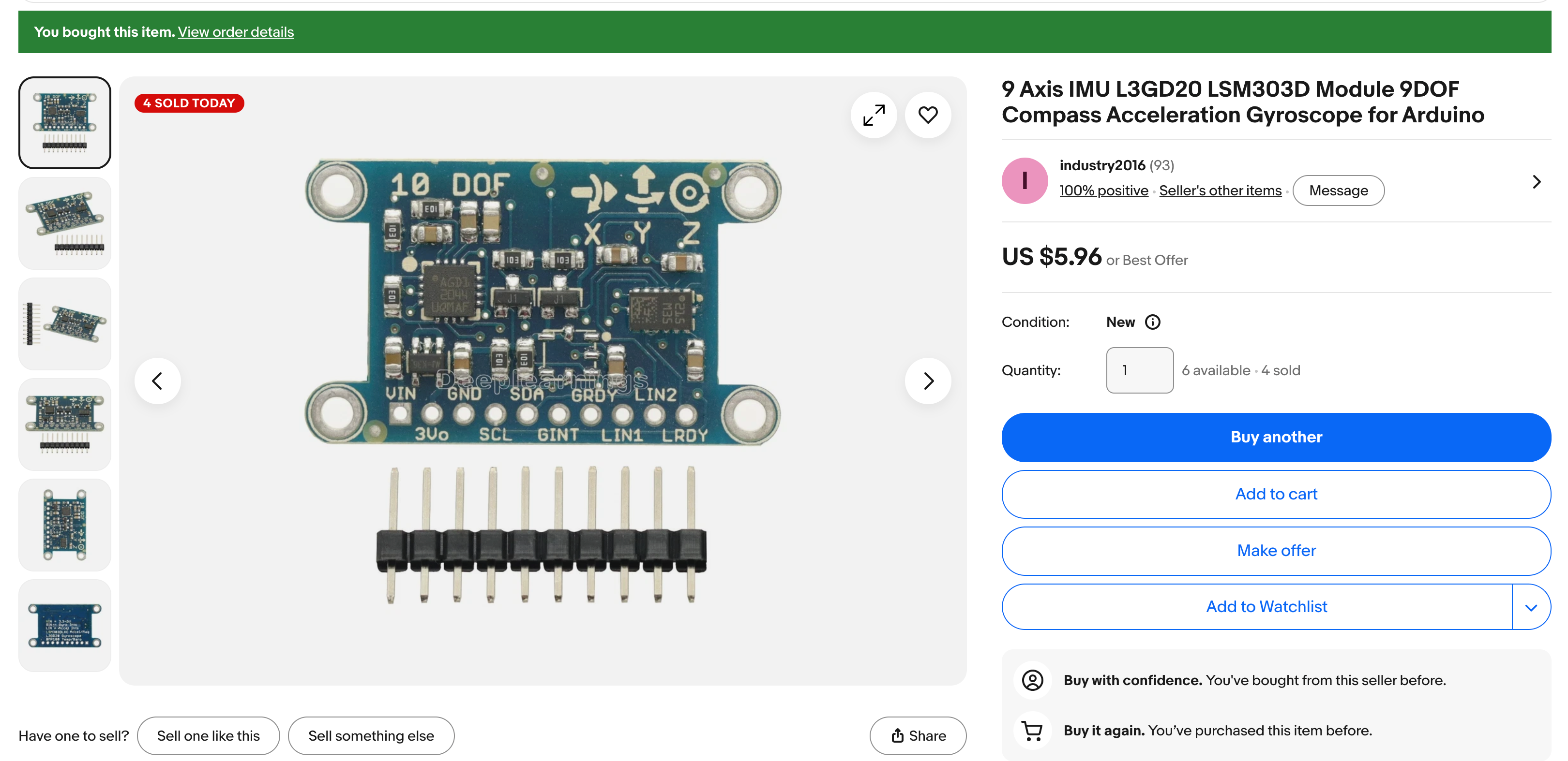 The purchased module. Two separate ST chips on one board — a gyroscope (L3GD20) and a combined accelerometer/magnetometer (LSM303DLHC, which answers at two I2C addresses) — plus a bonus BMP180 pressure sensor that this project doesn't use.
1. What Changes From the Design Report
The design report's generic bill of materials assumed a separate motor driver
(TB6612FNG). The ROBO-PICO already has an onboard dual motor driver, LiPo charge
circuit, buzzer, NeoPixel, and five Grove ports — all visible on its pinout diagram
and already used by other kits in this repo (src/kits/wi-fi-bot/config.py,
src/kits/base-bot/config.py). That simplifies the per-robot BOM to just:
| Item | Status |
|---|---|
| Cytron ROBO-PICO board | On hand (existing kits use it) |
| Raspberry Pi Pico W | On hand |
| L3GD20 + LSM303DLHC 9-DOF module ("10 DOF" silkscreen, bonus BMP180) | Purchased ($5.96), bench-tested in 9-dof-imu |
| Two DC gear motors + wheels + caster + chassis | On hand (existing kit chassis) |
| LiPo battery | On hand |
| 10-pin male header (to solder onto the IMU) | Included loose with the module — must be soldered before wiring |
Reference: Cytron ROBO-PICO datasheet — pin functions, onboard peripherals, and electrical specs for the board.
The class already solders sensor boards regularly, so the unsoldered header is a normal first step, not a blocker.
2. IMU Identification and Pinout
The module's silkscreen pin labels (top row, left to right): VIN, GND, SDA, GRDY, LIN2.
Bottom row: 3Vo, SCL, GINT, LIN1, LRDY. The back of the board lists its chips: an
L3GD20 gyro, an LSM303DLHC accel/mag, and a bonus BMP180 temperature/pressure
sensor (hence "10 DOF" on the silkscreen). An earlier draft of this plan assumed the
newer LSM303D, which has a single address (0x1D) and a different register map; the
bench probe (src/kits/9-dof-imu/01-probe.py) confirmed the LSM303DLHC, whose
accelerometer (0x19) and magnetometer (0x1E) are separate I2C sub-devices. Use the
LSM303DLHC datasheet, not LSM303D references, when you get stuck. The board silkscreen
also prints X/Y/Z axis arrows — use those, not guesswork, to decide which physical edge
is "front" when you mount it.
We only need four of the ten pins for the first build. The GRDY, LIN2, GINT,
LIN1, and LRDY interrupt/data-ready pins are a stretch goal (Section 5, Phase 12) —
leave them unconnected for now and poll the sensors instead.
3. Wiring
Wire the IMU to the same I2C bus already used by the ToF sensor and OLED display in
other ROBO-PICO kits (I2C_SDA_PIN = 16, I2C_SCL_PIN = 17 in every existing
config.py). I2C allows multiple devices on one bus as long as addresses differ, and
this module presents two.
| IMU pin | ROBO-PICO pin | Notes |
|---|---|---|
VIN |
3V3 (GPIO breakout header) |
Start with 3.3V. Before connecting SDA/SCL to the Pico, check with a multimeter that SCL reads ~3.3V idle-high — some clone boards' onboard regulators need more headroom and only work cleanly off 5V (VBUS). If the scan in Phase 1 below finds nothing, try VBUS instead. |
GND |
GND |
|
SDA |
GPIO16 |
Shared with existing I2C_SDA_PIN |
SCL |
GPIO17 |
Shared with existing I2C_SCL_PIN |
GRDY, LIN2, GINT, LIN1, LRDY |
unconnected | Reserved for interrupt-driven reads (stretch goal) |
The bench-test kits wire this same module to a bare Pico on different pins —
src/kits/9-dof-imu uses GPIO0/1 and src/kits/9-dof-imu-display uses GPIO12/13 —
because they have no Grove bus to share. The chip, addresses, and drivers are identical;
only I2C_SDA_PIN/I2C_SCL_PIN in each kit's config.py differ. Use machine.SoftI2C
rather than machine.I2C for this module: on the bench, the hardware I2C0 peripheral
scanned all four chips but threw OSError: EIO on every real read, while SoftI2C on the
same pins worked at every frequency tested.
Mount the module away from the DC motors — motor magnets distort the magnetometer, and this is the single most common cause of a heading that drifts or jumps only while driving. A small standoff on the rear deck, away from both motors, is enough.
4. Software Layout
Follow the numbering convention already used in src/kits/base-bot/ and src/kits/wi-fi-bot/.
Proposed new files:
1 2 3 4 5 6 7 8 9 10 11 12 13 14 15 | |
Add to config.py:
1 2 3 4 5 6 7 8 9 10 | |
5. Step-by-Step Build Order
Phase 0 — Bench setup (once, per robot)
- Flash MicroPython onto the Pico W (same image already used for the wifi-bot kit).
- Confirm the base robot still works: motor test buttons on the ROBO-PICO, and the
existing
01-wi-fi-test.pyconnects to your classroom WiFi. - Solder the 10-pin header onto the IMU module.
Phase 1 — Confirm both IMU chips answer on I2C
- Wire the IMU per Section 3.
- Run the existing I2C scanner pattern (
src/kits/base-bot/09-i2c-scanner-test.py) but print all devices found, not just the first:
1 2 3 4 | |
Expect four addresses (plus the ToF sensor's, if it's on the same bus): the gyro at
0x6B (or 0x6A if its SDO pin is grounded on this particular clone), the
LSM303DLHC accelerometer at 0x19 and magnetometer at 0x1E, and the unused BMP180
at 0x77. Record whatever you actually see and update config.py — don't assume
the datasheet default.
3. Confirm chip identity — src/kits/9-dof-imu/01-probe.py already does all three:
the gyro's WHO_AM_I register (0x0F) should read 0xD4 (L3GD20) or 0xD7
(L3GD20H); the magnetometer's identification registers 0x0A–0x0C should spell
"H43"; the accelerometer has no identity register, so write CTRL_REG1_A (0x20)
and confirm it reads back. A mismatch means the wrong address or a wiring fault, not
a bad filter later on.
Phase 2 — Drivers (already written)
The shared drivers src/lib/l3gd20.py and src/lib/lsm303dlhc.py already exist,
follow the register-constant style of src/lib/VL53L0X.py (const() addresses,
readfrom_mem/writeto_mem), and were bench-tested on this exact module in the
9-dof-imu kit. The swarm kit's upload-code.sh should copy
them into lib/ on each robot, the same way the bench kit does:
1 2 3 4 5 6 7 8 9 | |
Two LSM303DLHC quirks the driver already handles: the magnetometer's output registers
come out in X, Z, Y order, and X/Y and Z have different sensitivities at the ±1.3 gauss
setting. Re-check the gyro sensitivity against the WHO_AM_I result from Phase 1
(L3GD20 vs L3GD20H have slightly different specs), and be ready to adjust after
Phase 3's raw-value sanity check.
Phase 3 — Raw sensor read test (03-read-accel-mag-raw.py)
Print gyro deg/s, accel g's, and mag gauss in a loop. Sanity checks before moving on:
- Accelerometer magnitude ≈ 1.0 g while the robot sits still.
- Gyro readings ≈ 0 dps while still, and change sign when you rotate the robot the other way.
- Magnetometer magnitude stays roughly constant as you rotate the robot in place (only the X/Y split should change, not the overall size).
Phase 4 — Magnetometer calibration (04-mag-calibration.py)
This is the step the design report flags as the most common reason heading-following demos fail — don't skip it.
- Place the assembled robot on a table, away from motors of other robots and away from laptops/metal.
- Run a script that logs
mag_x, mag_yfor ~20 seconds while you slowly spin the robot by hand through at least one full rotation. - Compute the hard-iron offset:
offset_x = (max_x + min_x) / 2,offset_y = (max_y + min_y) / 2. - Apply the offset before every heading calculation:
corrected_x = mag_x - offset_x,corrected_y = mag_y - offset_y. - Save the two offsets per robot — in
config.pyor a smallcalibration.json— since each robot's soldering and mounting is slightly different. Start with hard-iron correction only; add soft-iron (per-axis scale) correction only if heading error is still too large after this. - Re-run this whole step any time the IMU is unmounted, remounted, or moved.
Phase 5 — Heading fusion (05-heading-fusion-test.py, heading_filter.py)
A complementary filter is enough — no need for a full Kalman filter for this project:
1 2 3 4 5 6 7 8 9 10 11 12 13 14 15 16 17 18 | |
Blend the signed shortest-path difference, not the two raw 0–359° values.
alpha * gyro + (1 - alpha) * compass is algebraically the same as
gyro + (1 - alpha) * (compass - gyro), but only the second form can be wrapped:
blending raw values near north fails (359° and 1° at alpha = 0.98 gives ~352°
instead of ~359°), while the wrapped diff gives +2° and nudges the heading the short
way. It's the same wrap trick heading_error() uses in Phase 9.
Run the fusion loop at LOOP_HZ (50 Hz → dt = 0.02). alpha = 0.98 is a reasonable
starting point: mostly trust the gyro moment-to-moment, and let the (calibrated)
compass slowly correct drift.
Phase 6 — Validate a stable heading
Rotate the robot by hand to known headings — use a phone compass app or a printed compass rose as ground truth — and confirm the reading is within about 10–15° after calibration. Leave the robot still for 60 seconds and confirm the heading doesn't drift. Then power the drive motors and confirm the heading doesn't jump — if it does, the IMU is too close to the motors; add a standoff and recalibrate.
Phase 7 — Master: WiFi AP + UDP broadcast (06-master-ap-broadcast.py)
Reuse the network / socket patterns already in src/kits/wi-fi-bot/, but in
Access-Point mode broadcasting UDP instead of Station mode serving a TCP web page:
1 2 3 4 5 6 7 8 9 10 11 12 13 14 15 16 17 18 19 20 21 22 23 | |
Phase 8 — Follower: join AP + UDP receive (07-follower-udp-receive.py)
1 2 3 4 5 6 7 8 9 10 11 12 13 14 15 16 17 18 19 20 21 22 23 24 25 26 27 28 | |
Phase 9 — Follower steering (08-follower-pid-steering.py)
Normalize the heading error to the shortest turn direction, then apply a proportional (start simple, add I/D only if needed) controller:
1 2 3 4 5 6 7 8 9 | |
Feed left/right into the existing motor pins from config.py
(RIGHT_FORWARD_PIN, LEFT_FORWARD_PIN, etc.) — same PWM pattern already used in
src/kits/base-bot/04-motor-test.py.
Phase 10 — Two-robot integration test (09-swarm-integration-test.py)
One robot running the master script, one running the follower script, both on the bench. Manually rotate the master and confirm the follower turns to match within a second or two.
Phase 11 — Scale to 3+ followers
Flashing the same follower code to more robots is "free" in principle, since UDP broadcast needs no per-follower registration. In practice, test this early: the Pico W's onboard soft-AP has a real limit on simultaneous associated stations (commonly cited around 4 in community testing, not officially documented by Raspberry Pi). If the class's follower count exceeds what the Pico-hosted AP handles reliably, the fallback is a dedicated WiFi router or access point as the network — the UDP broadcast payload and follower code don't need to change, only which device hosts the AP.
Phase 12 — Extension ideas
- Tilt-compensated heading: use the accelerometer (already on this same chip as the magnetometer) to correct the compass heading when the robot isn't level — useful if the swarm ever operates on a ramp or uneven floor.
- Bump/collision detection: the accelerometer is already being read every loop; a spike above ~1.5g is a free collision signal with no extra hardware.
- Forward speed matching, obstacle avoidance, and loose formation offsets, as listed in the design report.
- Interrupt-driven reads using
GRDY/LRDYinstead of polling, if loop timing becomes tight with more sensors added later.
6. Troubleshooting Checklist
| Symptom | Likely cause |
|---|---|
| I2C scan finds nothing | Check VIN/GND wiring first; try VBUS (5V) instead of 3V3 if the onboard regulator needs more headroom |
| I2C scan finds only one address | One chip's WHO_AM_I read failed — re-check solder joints on that chip's side of the board |
WHO_AM_I doesn't match expected value |
Wrong address assumed, or a cold solder joint — don't proceed to calibration until this passes |
| Heading drifts slowly while stationary | Re-run magnetometer calibration (Phase 4) |
| Heading jumps only while driving | IMU mounted too close to a motor — add a standoff, recalibrate |
| Two robots report different headings for the same physical orientation | Expected — per-robot calibration and solder variance. This is the sensor-variance teaching point from the design report, not a bug |
| Follower never turns | Confirm follower joined the master's AP subnet (ifconfig()), and that UDP_PORT matches on both sides |
| Follower steering oscillates / hunts | Kp too high — reduce it, or add a small deadband around zero error |
7. Suggested Session Schedule
Assuming roughly 45–60 minute class blocks:
- Solder headers, wire IMU, confirm I2C scan +
WHO_AM_I(Phase 0–1) — one session. - Raw sensor read + sanity checks (Phase 2–3) — one session.
- Magnetometer calibration (Phase 4) — one session; this one tends to need re-runs.
- Heading fusion + validation (Phase 5–6) — one session, a good milestone to celebrate on its own, matching the design report's suggested build order.
- Master AP broadcast + follower receive, single pair (Phase 7–10) — one to two sessions.
- Scale to the full swarm + extensions (Phase 11–12) — remaining sessions.