Synthesizing Robot Sounds
Let's make a robot that talks back!
 R2-D2 never says a word, yet you always know how he feels. In this kit
you will build those feelings out of one wire and a handful of numbers -
no sound files, no audio chip, and almost no money.
R2-D2 never says a word, yet you always know how he feels. In this kit
you will build those feelings out of one wire and a handful of numbers -
no sound files, no audio chip, and almost no money.
Summary
This kit makes R2-D2 style robot sounds using a single GPIO pin. There is no audio chip and no recorded sound stored on the Pico. Instead, the Pico switches one pin on and off very fast, and how fast it switches is the pitch you hear.
A sound chip that plays real recordings can cost as much as the whole robot controller board. This kit trades away that recorded quality and keeps the parts that carry the feeling: the way a pitch slides, the way a sound swells and fades, and the rhythm of the beeps. Those three things are where a robot's personality actually lives.
What You Need
| Part | Notes |
|---|---|
| Raspberry Pi Pico | Any model, running MicroPython |
| XPT8871 amplifier module | A small mono board that runs on 5 volts |
| Speaker | 4 to 8 ohms |
| 1 kΩ resistor | Called R1 in the diagram |
| 100 Ω resistor | Called R2 |
| 470 nF capacitor | Called C1 |
| 10 µF capacitor | Called C2 |
| Momentary push button | Plays the next sound |
Building a robot on a Cytron Maker Pi RP2040? You can skip every part in this table except the button. That board already has a small piezo buzzer wired to GPIO 22, so the sounds cost you nothing at all. They are thinner and quieter, but they work.
The Amplifier Board
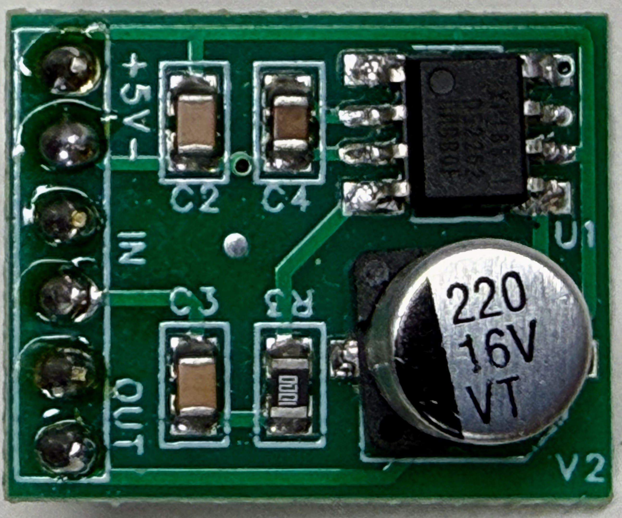
Find the six holes down the left edge. They are grouped in pairs, and the white lettering names them: +5V and - at the top for power, IN in the middle for the sound coming from the Pico, and OUT at the bottom for the speaker.
Now look for a volume knob. There isn't one. That is the most important thing about this board, and it is why the circuit below needs two resistors instead of one: nothing on the amplifier turns the sound down, so you have to hand it a signal that is already the right size.
The silver can marked 220 16V is a capacitor that steadies the power supply, and it is already fitted. You do not need to add capacitors of your own across the power pins.
Wiring the Sound Circuit
Only four small parts sit between the Pico and the amplifier. Two of them set how loud the signal is, and two of them clean it up.
Diagram: Synth Sounds Input Filter
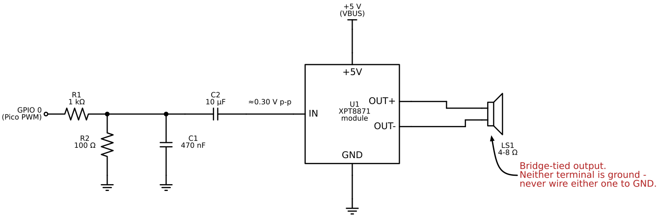
R1 and R2 make the signal smaller. The Pico's pin swings a full 3.3 volts, but the amplifier expects something closer to 0.3 volts and makes everything it hears about twenty times louder. Hand it the full 3.3 volts and it runs out of room, squaring off the tops of the sound into a harsh buzz. These two resistors divide the signal by eleven so the amplifier gets a size it can handle.
C1 rounds off the sharp corners. A pin that is only ever on or off makes a square-edged wave, and those hard edges sound scratchy. C1 softens them.
C2 blocks the steady voltage. The signal from the Pico rides on top of a constant voltage that the amplifier does not want. C2 lets the changing part - the sound - pass through and holds the steady part back.
Never connect a speaker wire to ground
 This amplifier drives both speaker wires at once, so neither one is
ground. Connect the speaker across the two output terminals and to
nothing else. Wiring either one to ground can destroy the amplifier
chip - and so can touching one with a grounded oscilloscope probe.
This amplifier drives both speaker wires at once, so neither one is
ground. Connect the speaker across the two output terminals and to
nothing else. Wiring either one to ground can destroy the amplifier
chip - and so can touching one with a grounded oscilloscope probe.
If the Pico restarts when the sound gets loud
 That is not a bug in your program. A loud speaker pulls more current
than a USB port likes to give. Turn the volume down, or give the
amplifier its own 5 volt supply and connect the two grounds together.
That is not a bug in your program. A loud speaker pulls more current
than a USB port likes to give. Turn the volume down, or give the
amplifier its own 5 volt supply and connect the two grounds together.
How a Sound Is Stored
Every sound in this kit is a short list of segments. Each segment is five numbers:
1 | |
The pitch slides in a straight line from freq_start to freq_end while the
volume fades from volume_start to volume_end. A segment with a frequency
of 0 is a silence. That one pattern describes a chirp, a beep, a wobble, and a
pause - and the whole sad sound takes only eight of them.
These numbers were not guessed. A program measured the pitch and loudness of real recorded R2-D2 sounds many times a second, then squeezed each recording down to a few segments. When you play one, you are hearing a measurement of the original.
One pin, sixteen feelings
 All sixteen sounds together take about 50 kB of memory and no storage
space at all. The same Pico pin that blinks an LED can carry every one
of them.
All sixteen sounds together take about 50 kB of memory and no storage
space at all. The same Pico pin that blinks an LED can carry every one
of them.
The Labs
Work through these in order. Each one builds on the last.
| Lab | What you build |
|---|---|
| Lab 1: Build the Sound Circuit | Wire the amplifier and play your first note |
| Lab 2: Sliding Pitches | Make a beep sound curious, then disappointed |
| Lab 3: Shaping the Volume | Get soft and loud out of an on/off pin |
| Lab 4: Sounds From Measurements | Play all sixteen sounds and read one as data |
| Lab 5: Add the Button | Wire an input and catch it bouncing |
| Lab 6: The Sound Jukebox | Finish the device and cut the cord |
The code for this kit lives in src/kits/synth-sounds/, along with the tools
that measured the recordings and the schematic source for the diagram above.