Lab 1: Build the Sound Circuit
Most robot kits make sound with an audio chip that costs more than the robot's brain. This kit does not use one. You will build a sound system from one wire, two resistors, two capacitors, and a tiny amplifier board. By the end of this lab your speaker will play a real musical note.
Welcome, maker!
 We're going to make me talk using a single pin — no sound chip at all.
Four little parts stand between my brain and the speaker, and by the
end of this lab you'll know what every one of them does.
We're going to make me talk using a single pin — no sound chip at all.
Four little parts stand between my brain and the speaker, and by the
end of this lab you'll know what every one of them does.
What You Need
- A Raspberry Pi Pico with MicroPython already installed
- A solderless breadboard and jumper wires
- An XPT8871 mono amplifier board
- A speaker, 4 to 8 ohms
- One 1 kΩ resistor and one 100 Ω resistor
- One 470 nF capacitor and one 10 µF capacitor
- A computer with Thonny installed
What You'll Learn
- How a single on/off pin can make a musical note
- Why the signal must be made smaller before it reaches the amplifier
- What a voltage divider is and how to read one
- Why a speaker wire must never touch ground on this amplifier
Step-by-Step
Step 1: Find the Pins on the Amplifier
Look at the amplifier board. Six holes run down one edge in three labelled pairs.
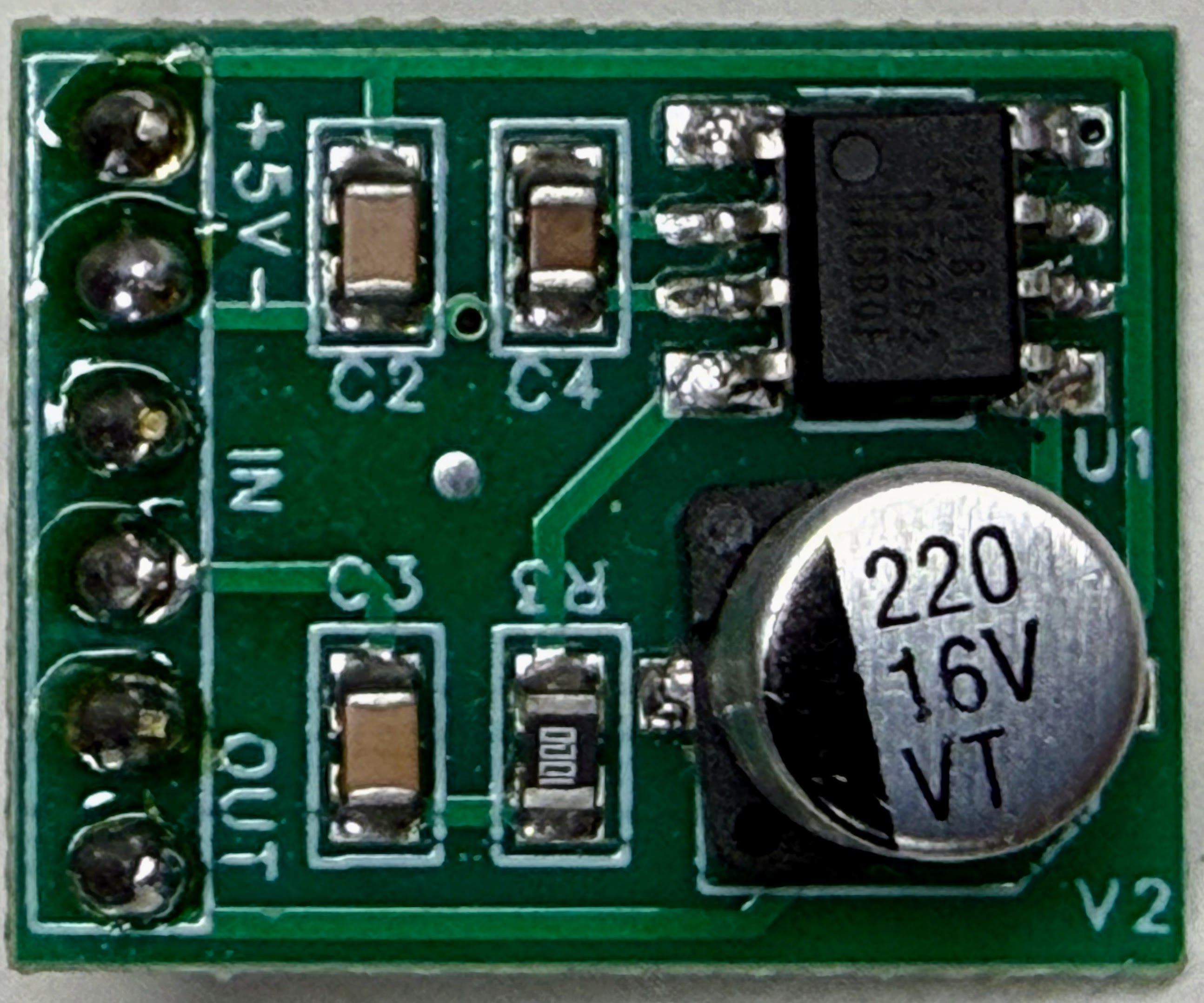
The white lettering names them: +5V and − for power, IN for the sound coming from the Pico, and OUT for the speaker.
Now look for a volume knob. There isn't one. That missing knob is the reason this circuit needs two resistors instead of one.
Step 2: Study the Circuit You Are About to Build
Four small parts sit between the Pico's pin and the amplifier's IN hole.
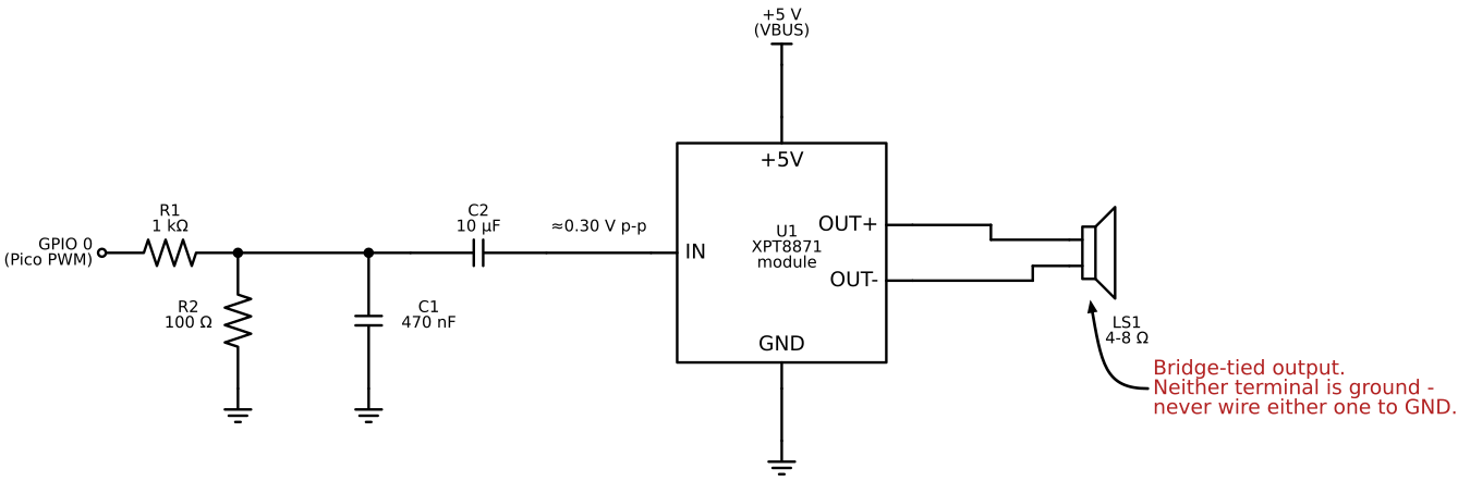
Read the diagram from left to right. The signal starts at GPIO 0, passes through R1, reaches a junction, and continues through C2 into the amplifier. R2 and C1 both connect from that junction down to ground.
Step 3: Understand Why the Signal Must Shrink
The Pico's pin swings a full 3.3 volts — that is its only choice, because a pin is either fully on or fully off.
The amplifier expects something much gentler, around 0.3 volts, and it makes everything it hears about twenty times louder. Hand it the full 3.3 volts and it runs out of room. The tops and bottoms of the sound get squared off flat, which your ears hear as a harsh, gritty buzz.
R1 and R2 form a voltage divider — two resistors in a row that split a voltage into a smaller share. The share that reaches the amplifier is the bottom resistor divided by both together:
1 | |
So 3.3 volts arrives as about 0.30 volts. That is a size the amplifier can handle without running out of room.
Why not just turn the volume down in the code?
 Software can change how wide my pulses are, but never how tall
they are — a pin is always either 0 V or 3.3 V. Making the signal
shorter is a job only resistors can do.
Software can change how wide my pulses are, but never how tall
they are — a pin is always either 0 V or 3.3 V. Making the signal
shorter is a job only resistors can do.
Step 4: Understand the Smoothing Capacitor
A pin that is only ever on or off makes a square wave — a signal with hard, vertical edges. Those sharp corners sound scratchy.
C1 rounds them off. It sits between the junction and ground, and it passes very fast wiggles straight to ground while leaving slower ones alone. The result is a softer, rounder wave.
C2 does a different job. The signal from the Pico rides on top of a steady voltage that the amplifier does not want. C2 lets the changing part through — that is the sound — and holds the steady part back.
Step 5: Wire It Up
Build the circuit with the power disconnected. Work left to right along the diagram.
- Jumper from the Pico's GP0 to one end of R1.
- Connect the other end of R1 to an empty breadboard row. This row is the junction.
- From that junction, connect R2 down to the ground rail.
- Also from that junction, connect C1 down to the ground rail.
- From that junction, connect C2 across to the amplifier's IN hole.
- Connect the Pico's GND to the amplifier's − hole.
- Connect the Pico's VBUS to the amplifier's +5V hole.
- Connect the speaker across the amplifier's two OUT holes.
Never connect a speaker wire to ground
 Heads up — this one surprises a lot of engineers. This amplifier
drives both speaker wires at once, so neither one is ground. Wire
the speaker across the two OUT holes and to nothing else. Touching
either one to ground can destroy the chip.
Heads up — this one surprises a lot of engineers. This amplifier
drives both speaker wires at once, so neither one is ground. Wire
the speaker across the two OUT holes and to nothing else. Touching
either one to ground can destroy the chip.
Step 6: Check Your Ground Before Powering Up
Two ground mistakes are easy to make on a breadboard, and both make the sound noisy.
First, many breadboards split their power rails in the middle. If yours does and you have not bridged the halves, ground at one end is not actually connected to ground at the other. Check your board and add a bridging wire if it needs one.
Second, bring R2's leg, C1's leg, and the Pico's GND wire to the same area of the ground rail as the amplifier's − hole. The amplifier measures its input against its own ground pin, so that is the ground your circuit should share.
Step 7: Make Your First Sound
Connect the Pico to your computer with the USB cable and open Thonny.
Open 01-first-beep.py and press the green Run button.
1 | |
This line plays a steady 440 Hz note for 400 milliseconds. You should hear three notes in a row: one in the middle, one higher, one lower.
If you hear nothing, check the speaker wires first, then the VBUS connection.
Try It Yourself
- Change
440to880and run it again. Doubling a frequency raises the pitch by exactly one octave, every time. - Change it to
220. That is half of 440, so it drops one octave. - Try
50. Can you still hear it? Small speakers are poor at low notes. - Swap R2 for a 220 Ω resistor. The sound gets louder, because a bigger bottom resistor keeps a bigger share of the signal.
What's Happening Under the Hood
The Pico is switching GP0 on and off 440 times each second. That switching pushes and pulls the speaker cone 440 times each second, and your ear reads that rate as a musical pitch. The technique is called PWM, short for Pulse Width Modulation.
Everything between the pin and the amplifier exists to turn that harsh electrical switching into something a speaker can play pleasantly. The resistors set the size, and the capacitors set the shape.
Check Your Understanding
- How many volts does the Pico's pin swing, and how many does the amplifier want?
- What do we call two resistors that split a voltage into a smaller share?
- What does C1 do to the sharp edges of a square wave?
- Why must neither speaker wire touch ground on this amplifier?
- Name one ground mistake that is easy to make on a breadboard.
Full Code
You can find the complete program at
src/kits/synth-sounds/01-first-beep.py.
Your circuit works!
 Double thumbs-up! You just built an audio system out of four parts and
a single pin — and you know what every one of those parts is for.
That's real electronics engineering!
Double thumbs-up! You just built an audio system out of four parts and
a single pin — and you know what every one of those parts is for.
That's real electronics engineering!