Electricity Basics: Voltage, Current, and Resistance
Summary
This chapter introduces the core electrical quantities that every later chapter depends on: electric current, voltage, resistance, and Ohm's Law, along with basic circuit types and terminal/lead vocabulary. It is the true starting point of the course — no other chapter can be understood without these ideas. By the end, students will recognize and name the most fundamental building blocks of any circuit.
Concepts Covered
This chapter covers the following 19 concepts from the learning graph:
- Electric Current
- Voltage
- Resistance
- Ohm's Law
- Power
- Direct Current
- Circuit
- Open Circuit
- Closed Circuit
- Short Circuit
- Series Circuit
- Parallel Circuit
- Ground
- Polarity
- Circuit Diagram
- Schematic Symbol
- Component Lead
- Positive Terminal
- Negative Terminal
Prerequisites
This chapter assumes only the prerequisites listed in the course description.
Your New Superpower
Every builder, inventor, and engineer who has ever lit up an LED, spun a motor, or made a robot blink started in exactly the same place you're starting right now: not knowing how electricity works. By the end of this chapter, you'll understand it well enough to talk about it like a pro — and that knowledge is your personal superpower. Once you can see how current, voltage, and resistance work together, you'll never look at a battery, a wire, or a light switch the same way again.
Meet Volt!
 Hi there — I'm Volt! I'm a small, friendly robot, and I happen to be absolutely delighted about electronics (my eyes literally glow when I get excited, so you'll always know). I'll be popping up throughout this book, but only when I've got something useful to do. Here's my job description, in seven parts:
- Welcome — I show up at the start of every chapter to tell you what's coming and cheer you on.
- Thinking — I pause the action at key concepts to make sure the big idea really lands.
- Tip — I hand you shortcuts, memory tricks, and hints that make building easier.
- Warning — I flag the mistakes that trip up almost every beginner, so you can skip right past them.
- Encourage — I show up when something feels tough, to remind you that struggling is just part of building.
- Celebration — I throw a little party at the end of chapters and big sections, because you earned it.
- Neutral — the rest of the time, I'm just hanging around in the margins for general notes.
If I'm not doing one of those seven things, I'm not popping up — I promise not to clutter your reading. Ready, builder? Let's light it up!
What Is Electricity, Really?
Everything in the universe, including the pages of this book and your own body, is made of atoms. Each atom has a center (called a nucleus) surrounded by tiny, negatively charged particles called electrons. In some materials — especially metals like the copper inside a wire — electrons aren't tightly bound to their atoms. They can be nudged loose and pushed along from atom to atom.
Electric current is the flow of these electrons through a material. When billions of electrons drift steadily in the same direction through a wire, you get a current — the same way a steady stream of water molecules flowing through a pipe makes a current of water. Current is measured in a unit called the amp (short for ampere), and it's the "how much electricity is moving" number for any circuit.
Electricity can flow in two different patterns. Alternating current (AC) — the kind that comes out of a wall outlet — reverses direction many times per second. This course sticks entirely to the safer, simpler pattern: direct current (DC), where electrons flow steadily in a single direction, from a battery's negative side, through the circuit, and back to the positive side. Every project you build in this course — from batteries to USB power supplies — runs on DC, which is exactly why it's safe to build on a breadboard with your bare hands.
Before we go any further with definitions, let's build a mental picture that will carry you through the rest of this book.
The Water-Pipe Analogy
Electricity is invisible, which makes it tricky to picture in your head. Luckily, there's a classic trick that electronics teachers have used for decades: imagine electricity as water flowing through pipes. Water is something you can see, touch, and understand, and almost everything it does has a direct match in an electrical circuit.
Picture a water tower connected to a garden hose. A pump pushes water through the pipe, and a narrow section of pipe slows the flow down. Now swap in electrical language: a battery pushes electrons through a wire, and a resistor slows the flow down. That's the whole analogy in one sentence — everything else in this chapter is just filling in the details.
Here's how the three most important electrical quantities line up with their water-pipe equivalents:
| Electrical Quantity | Water-Pipe Equivalent | What It Measures |
|---|---|---|
| Voltage | Water pressure from the pump | How hard electrons are being pushed |
| Electric Current | Rate of water flow (liters per minute) | How much electricity is moving |
| Resistance | A narrow section of pipe | How much something fights the flow |
Try the interactive simulation below to see this analogy in motion — you can compare a pipe system side by side with an electrical circuit and watch how changing the "pressure" changes the flow.
Diagram: Water Flow Analogy MicroSim
Run the Water Flow Analogy MicroSim fullscreen
Water Flow Analogy MicroSim (reused MicroSim)
Type: microsim
sim-id: water-flow-analogy
Library: p5.js
Status: Reused
Source: https://dmccreary.github.io/circuits/sims/water-flow-analogy/
Source Repo: https://github.com/dmccreary/circuits/tree/main/docs/sims/water-flow-analogy
Reused from the MicroSim catalog (WHAT match score 0.7797). Bloom Taxonomy: Understand (L2). Bloom Verb: explain. Learning objective: Explain how voltage, current, and resistance in an electric circuit are analogous to pressure, flow rate, and pipe narrowness in a water system, by comparing an animated water-pipe system side by side with an animated electric circuit.
Voltage: The Push Behind the Current
Voltage is the electrical "push" that makes current move — just like water pressure is the push that makes water flow. Voltage is measured in volts (abbreviated V), and it's always measured between two points, such as the two ends of a battery. A fresh AA battery provides about 1.5 volts of push. A USB power supply provides 5 volts. The higher the voltage, the harder electrons get pushed — similar to how a taller water tower creates more pressure at the faucet.
Here's an important idea to hold onto: voltage by itself doesn't do anything. A battery sitting on a table, disconnected from everything, has voltage waiting inside it, but no current is flowing. Current only starts moving once you give the electrons a complete path to travel — which is exactly what a circuit provides, as you'll see in a few sections.
Resistance: Something in the Way
Resistance is anything that fights against the flow of current, the same way a narrow or clogged pipe fights against the flow of water. Resistance is measured in a unit called the ohm (written with the Greek letter Ω). Some materials, like copper wire, have very low resistance and let current flow almost freely. Other materials, like the coiled wire inside a toaster, have high resistance and turn a lot of that electrical push into heat.
In this course, you'll use small components called resistors constantly — they're one of the cheapest and most important parts in your $50 kit, precisely because they let you control how much current flows through a circuit on purpose.
The Three Amigos
 Voltage, current, and resistance always travel together — I like to call them the Three Amigos of electronics. Push harder (more voltage) and you get more flow (more current), unless something in the pipe (resistance) is fighting back. Once you can picture all three at the same time, the rest of this book gets a whole lot easier.
Ohm's Law: The Golden Rule of Circuits
Voltage, current, and resistance aren't just related in a general, hand-wavy way — they're connected by an exact mathematical rule called Ohm's Law, named after the German physicist Georg Ohm. Ohm's Law says that voltage equals current multiplied by resistance:
Ohm's Law
where:
- \( V \) is voltage, measured in volts (V)
- \( I \) is current, measured in amps (A)
- \( R \) is resistance, measured in ohms (Ω)
You don't need heavy math skills to use this rule — just multiplication and division of small numbers. If you know any two of the three values, Ohm's Law lets you calculate the third. For example, if a circuit has 5 volts of push and 100 ohms of resistance, you can calculate the current: \( I = V \div R = 5 \div 100 = 0.05 \) amps. That single equation is the reason every LED circuit in this course needs a resistor picked with the right value — too little resistance, and too much current tries to force its way through, which is exactly what damages components.
Try the calculator below. Adjust the sliders for voltage and resistance and watch the current update in real time, so you can build an intuitive feel for how the three quantities move together.
Diagram: Ohm's Law Circuit Simulator
Run the Ohm's Law Circuit Simulator fullscreen
Ohm's Law Circuit Simulator (reused MicroSim)
Type: microsim
sim-id: ohms-law-simulator
Library: p5.js
Status: Reused
Source: https://dmccreary.github.io/automating-instructional-design/sims/ohms-law-simulator/
Source Repo: https://github.com/dmccreary/automating-instructional-design/tree/main/docs/sims/ohms-law-simulator
Reused from the MicroSim catalog (WHAT match score 0.7929). Bloom Taxonomy: Apply (L3). Bloom Verb: calculate. Learning objective: Calculate an unknown value of voltage, current, or resistance given the other two, by adjusting voltage and resistance sliders and reading the resulting animated current and any overload warning.
A Handy Memory Trick
 Here's a trick a lot of builders use: draw a triangle, put V on top and I and R on the bottom. Cover up the letter you're solving for, and the triangle shows you the math — cover V and you see \( I \times R \); cover I and you see \( V \) over \( R \). No calculator required, just a triangle and a little algebra I'm happy to help you conduct.
Power: How Much Work Electricity Can Do
Voltage tells you how hard current is being pushed, and current tells you how much is flowing — but neither one alone tells you how much actual work a circuit is doing. That's the job of power, measured in watts (W). Power is calculated by multiplying voltage and current together:
Electrical Power
where:
- \( P \) is power, measured in watts (W)
- \( V \) is voltage, measured in volts (V)
- \( I \) is current, measured in amps (A)
Power is what turns electricity into something useful in the real world — light from an LED, spin from a motor, sound from a buzzer. A small LED might use a fraction of a watt, while a hair dryer uses well over a thousand watts. Every component in your kit has a maximum power rating, and part of being a careful builder is making sure a circuit never asks a component to handle more power than it's rated for.
The following components from your $50 kit each convert electrical power into a different kind of useful output:
- LEDs convert electrical power into light
- DC motors convert electrical power into spinning motion
- Buzzers convert electrical power into sound
- Resistors convert electrical power into heat (usually a very small, harmless amount)
What Is a Circuit?
Now that you know the Three Amigos and the golden rule that connects them, it's time to talk about the path they travel on. A circuit is a complete, connected loop that current can flow around — starting at a power source (like a battery), traveling through wires and components, and returning to the power source. Think of it as a racetrack: current only keeps moving if the track forms a full, unbroken loop.
Diagram: Closed, Open, and Short Circuit Paths
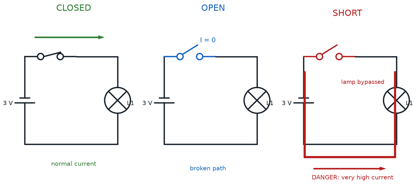
Circuits come in three important states, and every single one of them matters for troubleshooting your projects later in this course:
| Circuit State | What's Happening | Everyday Example |
|---|---|---|
| Closed Circuit | The loop is complete; current flows normally | Flipping a light switch to "on" |
| Open Circuit | The loop has a gap; no current can flow | Flipping a light switch to "off" |
| Short Circuit | Current finds an unintended low-resistance shortcut, skipping the parts meant to control it | A bare wire accidentally touching both battery terminals |
A closed circuit is a complete loop with no gaps — current flows all the way around, and whatever is in that loop (an LED, a motor, a buzzer) does its job. An open circuit has a break somewhere in the loop — maybe a switch is turned off, or a wire has come loose — and because the path isn't complete, no current flows at all, no matter how much voltage is available.
A short circuit is different from both of those, and it's the one every builder needs to watch out for. A short happens when current finds a path with almost no resistance at all — often because two bare wires touch each other directly, skipping over the resistor, LED, or motor that was supposed to control the flow. Since Ohm's Law says current increases when resistance drops, a short circuit can pull a sudden, large surge of current, which can drain a battery fast or make a wire uncomfortably hot.
Watch Out for Shorts!
 Never let a wire connect straight from the positive side of a power source to the negative side without a resistor, LED, motor, or other component in between. That's a short circuit, and it's the most common beginner mistake in this hobby. The good news: with the low-voltage batteries and USB supplies used in this course, a short circuit is more "startling and wasteful" than dangerous — but it's still a habit worth building correctly from day one.
Series and Parallel Circuits
Once you start connecting more than one component into a circuit, you get to choose how they're wired together — and that choice changes how current and voltage behave. There are two basic wiring patterns you'll use constantly throughout this course.
A series circuit connects components one after another along a single path, like beads on a single string. Every bit of current that flows through the first component has no choice but to flow through the next one too, since there's only one route available. A parallel circuit, on the other hand, connects components along separate branching paths, like several side-by-side lanes on a highway — current can split up and take more than one route at the same time.
Diagram: Series and Parallel Circuit Comparison
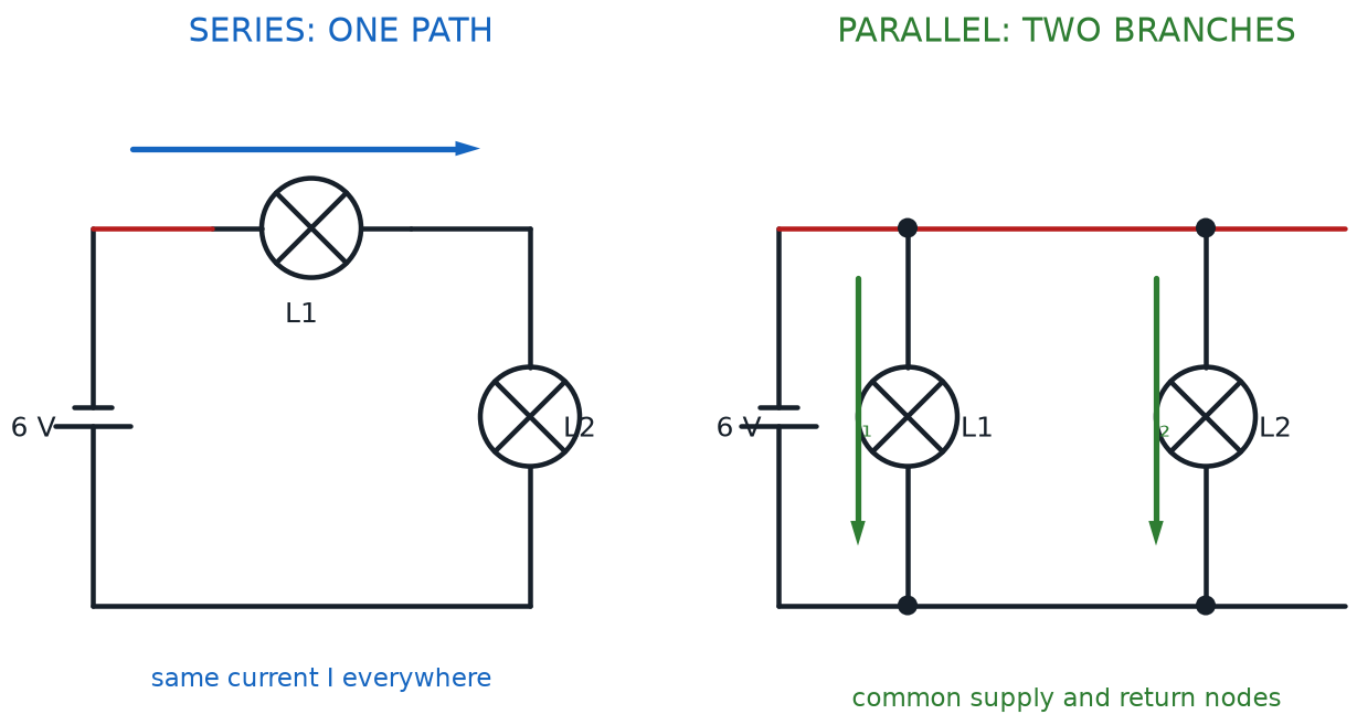
Here's how the two patterns compare:
- Series circuits have only one path for current, so the same current flows through every component; if one component fails or is removed, the entire loop breaks and everything stops
- Parallel circuits have multiple paths for current, so each branch can carry a different amount of current; if one branch breaks, current can still flow through the other branches
- Series circuits are simpler to wire but harder to troubleshoot, since one bad connection stops the whole circuit
- Parallel circuits let each component receive the full voltage from the power source independently, which is why household outlets are wired in parallel
Later in this course, you'll use both patterns on purpose: wiring buttons in series to build AND-like logic, and wiring buttons in parallel to build OR-like logic — all without writing a single line of code.
Ground and Polarity
Every circuit needs a shared reference point that all the voltages in the circuit are measured against — a kind of electrical "home base." That reference point is called ground. In a simple battery-powered project, the negative side of the battery is usually treated as ground, and every other voltage in the circuit is described relative to it (for example, "this point is 5 volts above ground").
Closely related to ground is the idea of polarity — the property of having a distinct positive side and a distinct negative side, so that a component or connection only works correctly one way. Not every component cares about polarity: a resistor works exactly the same no matter which way you wire it in. But many components absolutely do care, including batteries and LEDs, and wiring them backward is one of the most common reasons a first circuit doesn't light up.
Every DC power source has two connection points, and getting them right matters:
- The positive terminal is the connection point where conventional current is considered to exit the power source, usually marked with a plus sign (+) and, on many batteries, the longer or raised end
- The negative terminal is the connection point where current returns to the power source, usually marked with a minus sign (−) and, on many batteries, the flatter end
Polarity Is a One-Way Door
Picture polarity-sensitive components like a one-way door — current is only allowed to walk through in one direction. Batteries and LEDs both have this rule, which is exactly why checking positive and negative before you power up a circuit will save you a lot of head-scratching later in this course.
Reading the Blueprint: Circuit Diagrams and Schematic Symbols
Builders and engineers don't sketch every circuit as a realistic drawing of wires and parts — that would get messy fast. Instead, they use a circuit diagram (also called a schematic): a simplified map of a circuit that shows how components connect to each other using standardized symbols, without worrying about exactly how the wires will be physically arranged on a real breadboard.
Every component in a circuit diagram is drawn using a schematic symbol — a simple, standardized shape that represents a real part. A zigzag line means resistor, a triangle with an arrow means LED, two parallel lines of different lengths mean battery, and so on. Once you learn a symbol, you'll recognize it in any circuit diagram, from a simple LED project to a professional engineering drawing, because these symbols are used the same way worldwide.
On the real, physical version of a part, the wire ends that stick out and connect it to the rest of the circuit are called component leads. A resistor has two leads, and it doesn't matter which lead goes where, because a resistor has no polarity. An LED also has two leads, but — as you just learned — its leads absolutely are polarized, so getting them backward means the LED won't light up at all.
Explore the interactive circuit diagram below. Click each schematic symbol to see its name, what it represents, and whether polarity matters for that part.
Diagram: Circuit Diagram and Schematic Symbol Explorer
Circuit Diagram and Schematic Symbol Explorer
Type: infographic
sim-id: schematic-symbol-explorer
Library: p5.js
Status: Specified
Template: https://github.com/dmccreary/circuits/tree/main/docs/sims/circuit-symbol-flashcards
Purpose: Help students recognize the schematic symbols and terminal/lead vocabulary introduced in this chapter, and connect each symbol to the real component it represents.
Bloom Taxonomy: Remember (L1). Bloom Verb: identify.
Learning objective: Identify the schematic symbols for a battery, resistor, LED, switch, and ground connection, and label the positive terminal, negative terminal, and component leads on a simple circuit diagram.
Canvas layout: - Left/center (roughly 70% of width): a simple closed-loop circuit diagram drawn with standard schematic symbols — a battery, a resistor, an LED, and a switch, connected by wire lines into one loop, with a separate ground symbol shown off to the side - Right side (roughly 30% of width, stacking below the diagram on narrow screens): an infobox panel that displays information about whichever symbol was last clicked
Visual elements: - Battery symbol drawn with a long line (positive terminal) and a short line (negative terminal), each labeled with + and − when clicked - Resistor symbol drawn as a zigzag line with two leads - LED symbol drawn as a diode triangle-and-bar with two small arrows for emitted light, with the flat bar side (cathode) labeled as the negative lead when clicked - Switch symbol shown in its open position, with a small toggle control that lets the learner click the switch itself to flip it open/closed and see the wire gap appear or close - Ground symbol (three horizontal lines shrinking in width, or an inverted-triangle style symbol) shown connected to the circuit's negative reference point - A small "real component photo" thumbnail that appears in the infobox alongside each symbol's explanation, so learners connect the abstract symbol to the physical part
Interactive controls: - Click any symbol (battery, resistor, LED, switch, ground) to open its infobox - Click the switch specifically to toggle it open/closed; when open, an animated gap appears in the wire and a small "no current flowing" indicator appears; when closed, a subtle animated flow indicator moves around the loop - Hover over any wire segment to see a tooltip confirming whether current flows through it in the current switch state - Button: "Reset View" to close all infoboxes and return the switch to its default open position
Default parameters: - Switch starts open (circuit is an open circuit, no flow indicator) - No symbol pre-selected; infobox shows a "Click a symbol to learn about it" placeholder message
Behavior when a symbol is clicked: - Battery: infobox shows "Battery — the power source. The long line is the positive terminal; the short line is the negative terminal. Polarity matters!" - Resistor: infobox shows "Resistor — limits current flow. Has two component leads; no polarity, so it can be wired either way." - LED: infobox shows "LED (light-emitting diode) — converts electrical power into light. Has two component leads. Polarity matters: the flat-bar side is the negative lead." - Switch: infobox shows "Switch — opens or closes the circuit. Click me to toggle between an open circuit and a closed circuit." - Ground: infobox shows "Ground — the shared reference point that every voltage in the circuit is measured against."
Data Visibility Requirements: Stage 1 (default): Show the full circuit diagram with the switch open and no symbol selected, so the learner sees the whole "blueprint" first Stage 2 (symbol clicked): Show the selected symbol highlighted in the diagram plus its matching infobox text and thumbnail photo, side by side, so the learner can directly compare the abstract symbol to the real part Stage 3 (switch toggled closed): Show the animated flow indicator appear, tying the open/closed circuit vocabulary from earlier in the chapter back to a visible, concrete diagram
Instructional Rationale: This is a Remember-level objective (identify symbols and label terminals), so the interaction is deliberately a labeling/click-to-reveal pattern rather than a complex simulation. Progressive disclosure (click a symbol, see its definition and photo) matches how a beginner actually builds symbol recognition — one part at a time, with the option to revisit any symbol as often as needed.
Color scheme: Blue circuit lines and symbols on a light background; the positive terminal marked in warm orange, the negative terminal marked in a cool gray, matching the color logic used throughout the book so "positive" and "negative" are visually consistent everywhere a learner encounters them.
Responsive behavior: The circuit diagram and infobox panel must reflow into a stacked (diagram on top, infobox below) layout on narrow screens, and all symbols must remain clickable at any window width.
Implementation: p5.js, using clickable regions defined around each symbol's bounding box; infobox rendered as an HTML panel positioned beside (or below, on narrow screens) the p5.js canvas.
New Language, New Powers
 Schematic symbols can feel like learning a new alphabet at first, and that's completely normal — every engineer felt exactly the same way on day one. The good news is there are only a handful of symbols to learn in this course, and you'll see them again and again until they feel as familiar as street signs.
Chapter Summary: Key Takeaways
You've just covered the vocabulary that every remaining chapter in this course builds on. Before moving forward, make sure each of these ideas feels solid:
- Electric current is the flow of electrons through a wire, measured in amps, and it only moves when there's a complete path (a circuit) for it to travel
- Voltage is the electrical push behind that flow, measured in volts, similar to water pressure in the pipe analogy
- Resistance is anything that fights the flow, measured in ohms, similar to a narrow section of pipe
- Ohm's Law (\( V = I \times R \)) ties those three quantities together with one simple, reusable equation
- Power (\( P = V \times I \)), measured in watts, tells you how much actual work — light, motion, or sound — a circuit can produce
- Direct current (DC) flows steadily in one direction, which is the safe, simple kind of electricity used throughout this entire course
- A circuit can be closed (current flows), open (a gap blocks current), or shorted (current takes an unintended shortcut around the parts meant to control it)
- Series circuits wire components along one shared path; parallel circuits wire components along separate branching paths
- Ground is a circuit's shared voltage reference point, and polarity describes components (like batteries and LEDs) that only work correctly one way
- Every power source has a positive terminal and a negative terminal, and every physical component connects to the rest of a circuit through its component leads
- A circuit diagram uses standardized schematic symbols to map out a circuit without needing a realistic drawing of every wire
You now have the shared vocabulary that every builder, every kit instruction sheet, and every diagram in the rest of this book will assume you know. That's not a small thing — it's the foundation everything else stands on.
You Did It!
 Nice wiring, builder! You just unlocked the foundational superpower of every electronics project you'll ever build: the ability to read voltage, current, and resistance like a native language. Grab your kit — the next chapter is where you start putting these ideas into your own hands. Current's flowing your way!