Resistor Codes and Capacitor Details
Summary
Students learn to read a resistor's color bands and a capacitor's printed value code, and meet the different resistor and capacitor types (carbon film, metal film, electrolytic, ceramic, tantalum) they'll encounter while sorting their kit.
Concepts Covered
This chapter covers the following 19 concepts from the learning graph:
- Gold Tolerance Band
- Quarter Watt Resistor
- Carbon Film Resistor
- Metal Film Resistor
- Rheostat
- NTC Thermistor
- Axial Lead Package
- Radial Lead Package
- Capacitor Symbol
- Capacitor Value Code
- Microfarad
- Picofarad
- Nanofarad
- Capacitor Voltage Rating
- Capacitor Tolerance
- Tantalum Capacitor
- Non-Polarized Capacitor
- Capacitor Dielectric
- Bypass Capacitor
Prerequisites
This chapter builds on concepts from:
- 1. Electricity Basics: Voltage, Current, and Resistance
- 2. Current, Charge, Units, and Electrical Safety
- 5. Conductors, Batteries, and Circuit Vocabulary Review
- 9. Resistors and Capacitors
Chapter 9 promised the full resistor color code, and Chapter 10 cashed in a small piece of that promise — just four values, just four colors. This chapter finishes the job. By the end, you'll be able to look at any resistor from any kit, anywhere, and read its exact value and tolerance without guessing.
Capacitors get the same full treatment. Chapter 9 taught you to spot an electrolytic capacitor by its can shape and a ceramic capacitor by its disc shape, but never explained the tiny printed numbers on either one. That code is a language of its own, and once you can read it, every capacitor in your kit stops being a mystery part and starts being a labeled one.
Along the way you'll also meet a handful of specialized parts — resistors built from different materials, a thermistor that only goes one direction with temperature, and a capacitor type tough enough for precision circuits but touchy about which way it's wired. Consider this chapter your complete field guide to two of the most common parts in your kit.
The Complete Decoder Ring
 Welcome back, builder! Today you're finishing two decoder rings at once — the full resistor color code and the capacitor's numeric value code. Resist-ance is futile once you've got both of these memorized. Let's light it up!
Finishing the Resistor Color Code: All Ten Colors
Chapter 10 taught you four colors: brown, red, orange, and black. The real resistor color code uses ten colors, one for every digit from 0 to 9, and every resistor manufacturer on the planet uses the exact same ten.
The colors follow a pattern worth noticing instead of memorizing blindly. Black and brown open the sequence at 0 and 1, then red, orange, yellow, green, and blue march through the middle of the rainbow for 2 through 6, violet and gray cover 7 and 8, and white closes things out at 9. Once you've seen the pattern a few times, guessing an unfamiliar band's value gets a lot easier, even before you double-check it.
Group the Colors, Don't Just Memorize Them
 Try grouping the ten colors into pairs as you learn them: black/brown (0-1), red/orange (2-3), yellow/green (4-5), blue/violet (6-7), and gray/white (8-9). Five small pairs are much easier to lock in than one long list of ten.
The table below is the complete reference — every digit color, the multiplier band, and the tolerance colors, including the gold tolerance band this chapter's concept list singles out.
| Color | Digit Value | Multiplier | Tolerance |
|---|---|---|---|
| Black | 0 | ×1 | — |
| Brown | 1 | ×10 | ±1% |
| Red | 2 | ×100 | ±2% |
| Orange | 3 | ×1,000 | — |
| Yellow | 4 | ×10,000 | — |
| Green | 5 | ×100,000 | ±0.5% |
| Blue | 6 | ×1,000,000 | ±0.25% |
| Violet | 7 | ×10,000,000 | ±0.1% |
| Gray | 8 | ×100,000,000 | ±0.05% |
| White | 9 | ×1,000,000,000 | — |
| Gold | — | ×0.1 | ±5% |
| Silver | — | ×0.01 | ±10% |
Most resistors in your kit only use the tolerance colors in the last two rows. A gold tolerance band means the resistor's real value can drift up to 5% from its coded value, and a silver band allows up to 10% drift — both completely normal, not a sign of a defective part. If a resistor has no fourth band at all, its tolerance defaults to ±20%, the loosest and cheapest option.
Don't Read the Tolerance Band as a Digit
 Here's the mix-up almost every beginner makes at least once: mistaking the gold or silver tolerance band for a fourth digit band. Gold and silver never appear as digit or multiplier colors, only as tolerance — so if you spot one of those two colors anywhere on a resistor, that's your signal you've found the end of the code, not the middle of it.
Put the whole system to the test in the sim below — every color, every band, all at once.
Diagram: Full Resistor Color Code Decoder
Full Resistor Color Code Decoder
Type: microsim
sim-id: full-resistor-color-code-decoder
Library: p5.js
Status: Specified
Purpose: Let students decode any resistor's value and tolerance from any combination of the full ten-color digit code, the multiplier band, and the gold/silver tolerance band — the complete system promised back in Chapter 9 and narrowed to four values in Chapter 10.
Bloom Taxonomy: Apply (L3). Bloom Verb: calculate, decode.
Learning objective: Given a rendered resistor showing four color bands drawn from the complete ten-color digit code, the multiplier band, and a gold or silver tolerance band, calculate the resistor's exact value in ohms and its tolerance range.
Reuse check: An embeddings search (find-similar-templates, mode=reuse) for "Title: Full Resistor Color Code Decoder | Topic: Reading all ten resistor color code digit colors (black brown red orange yellow green blue violet gray white), multiplier band, and gold/silver tolerance band to determine a resistor's value | Subjects: Electronics, Beginning Electronics | Grade Level: Junior High | Learning Objectives: Given a resistor showing any of the ten color bands plus multiplier and tolerance bands, decode the full resistance value and tolerance range" returned a top match of "Resistor Color Code Calculator" (dmccreary/learning-micropython, WHAT score 0.6601, recommendation "template") — above the 0.60 template threshold but below the 0.75 reuse threshold, so this sim is a strong starting point to adapt rather than embed as-is. Template: https://github.com/dmccreary/learning-micropython/tree/main/docs/sims/resistor-color-code-calculator
A keyword grep of the 3,764-entry MicroSim catalog for "resistor color code" returned the same single match. Note for implementation: this repository's docs/sims/resistor-physical/draw-resistors.js already computes color bands FROM a resistance value (the reverse of what's needed here) and docs/sims/resistor/resistor.js draws the schematic zig-zag symbol rather than a physical banded body — both are library/reference documentation pages, not student-facing sims (confirmed the same finding Chapter 10 made), so they should be adapted as rendering building blocks rather than reused directly.
Canvas layout: Top area shows one large rendered resistor (tan body, four color bands, lead wires) centered on the canvas; below it, four clickable band-selector swatches, one per band position; a computed-value readout and infobox sit beneath the selectors.
Components/elements involved: A rendered physical resistor with four bands (digit 1, digit 2, multiplier, tolerance); four clickable color swatches, each cycling through its band's valid colors; a "Random Resistor" quiz button; a "Reveal Value" button; a computed-value readout.
Required interactivity: - Clicking any band's swatch cycles it through its valid colors (all ten digit colors for bands 1 and 2, ten multiplier colors plus gold/silver for band 3, gold/silver only for band 4); the rendered resistor and the computed-value readout update live with every click - Hovering any band on the rendered resistor opens an infobox stating that band's position and what its current color means (digit, multiplier power of ten, or tolerance percent) - Button "Random Resistor" sets all four bands to a random valid combination and hides the computed readout behind the "Reveal Value" button, so students can practice decoding by eye first - Button "Reveal Value" displays the computed resistance and tolerance range, formatted as "4,700 Ω ± 5% (4,465–4,935 Ω)" - Button "Reset" returns to the default state
Default state: Bands set to yellow-violet-red-gold (4,700 Ω ± 5%); infobox reads "Click any band to change its color, or hit Random Resistor to test yourself."
Instructional Rationale: An Apply-level "calculate/decode" objective is best served by a manipulable calculator where every band is independently adjustable, so students connect each individual color choice to its exact contribution to the final value, reinforcing the complete ten-color system after Chapter 10's four-color subset.
Color scheme: Accurate, true-to-life band colors for all ten digit/multiplier colors plus gold and silver; warm orange highlight on the currently hovered or selected band; green flash on "Reveal Value" consistent with this chapter's other diagrams.
Responsive behavior: The resistor illustration scales to canvas width; the four band selectors wrap into a single row on wide screens and a 2×2 grid on narrow screens; hover feedback also triggers on tap for touch devices.
Implementation: Plain p5.js, not the breadboard-sim-generator — this is a standalone component decoder rather than a wired circuit, the same choice Chapter 10 made for its kit-resistor-band-matcher sim. Extends the tan-body rendering approach from docs/sims/resistor-physical/ with a fourth (tolerance) band and the full ten-color set, plus click-to-cycle band selectors and computed-value logic.
Resistor Construction: Film Types, Power, and Packaging
Color bands tell you a resistor's value, but they don't tell you what the resistor is actually made of, or how much power it can safely handle. Those details matter too, and they're printed nowhere — you learn them by knowing the part.
A carbon film resistor is a resistor made by depositing a thin layer of carbon onto a ceramic core, the most common and least expensive way to build a fixed resistor. Carbon film resistors are perfectly accurate for this course's low-precision projects, but they're slightly noisier electrically and drift a bit more with temperature than their pricier cousin. A metal film resistor is a resistor made the same basic way, but with a thin layer of metal instead of carbon, giving it tighter tolerance, lower electrical noise, and better stability over time. Precision instruments and audio equipment favor metal film resistors; this course's general-purpose circuits work great with either type.
Power matters just as much as material. A quarter-watt resistor is a resistor rated to safely dissipate up to a quarter of a watt (0.25 W) of power as heat, the standard rating for nearly every resistor in this course's kit. At the low voltages and currents used throughout this book, a quarter-watt resistor has huge safety margin to spare — but larger projects with more current sometimes call for half-watt, one-watt, or even bigger resistors built with thicker bodies to shed more heat.
Every one of these resistors also shares the same physical packaging style. An axial lead package is a component package with one wire lead exiting from each end, in a straight line with the cylindrical body — the shape you've been picturing every time you've read a color band. Nearly every resistor you'll ever hold uses an axial lead package, which is exactly why the color bands wrap neatly around a tube shape with a lead sticking out of each side.
Same Value, Different Guts
 Here's a fact worth sitting with: a carbon film resistor and a metal film resistor can carry the exact same color bands and the exact same 220-ohm value, yet be built from completely different materials inside. The color code only ever describes the number — the material and the power rating are a separate story you learn from the datasheet or the parts bin label.
Resistors That Still React: Rheostat and NTC Thermistor
Chapter 9 introduced two resistors that change their value on their own: the photoresistor and the thermistor. Two more variable-resistance ideas round out the family, and both build directly on parts you've already met.
A rheostat is a two-terminal variable resistor used to control current directly, built the same way as a potentiometer but wired using only two of its three terminals instead of three. Where a potentiometer's wiper taps off a fraction of the total resistance for a voltage divider, a rheostat's wiper and one outer terminal work together to simply add more or less resistance in series with the current flowing through the circuit. Any potentiometer in your kit can become a rheostat just by leaving one terminal disconnected.
Chapter 9's thermistor comes in more than one flavor, and the kind you're most likely to hold in your hand has a specific name. An NTC thermistor is a thermistor whose resistance falls as its temperature rises — "NTC" stands for "negative temperature coefficient," meaning resistance and temperature move in opposite directions. NTC thermistors are by far the more common type in hobby kits and consumer electronics, which is why "thermistor" and "NTC thermistor" are often used almost interchangeably in casual conversation.
Diagram: Rheostat and Thermistor Control Circuits
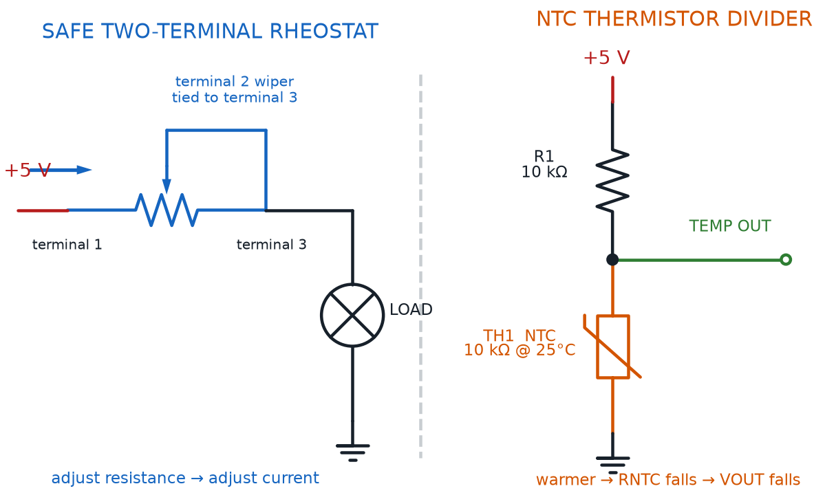
- Potentiometer — uses all three terminals to create an adjustable voltage divider
- Rheostat — uses only two terminals (the wiper plus one outer terminal) to add adjustable resistance directly in series with current
One Part, Two Jobs
You don't need a separate part to try a rheostat — grab your kit's trimmer potentiometer, wire only the wiper and one outer terminal into a circuit, and leave the third terminal disconnected. Same physical part, completely different job.
Meet the Capacitor Symbol and Its Package
Resistors get a zigzag symbol. Capacitors get something entirely different, and it comes in two versions depending on whether polarity matters.
The capacitor symbol is the schematic symbol for a capacitor: two parallel lines, one straight and the other either straight (for a non-polarized capacitor) or curved (for a polarized capacitor like the electrolytic capacitors from Chapter 9). The curved line always marks the negative side, a visual echo of the negative stripe printed on the real component. Spotting this symbol in a circuit diagram instantly tells you two things at once — that a capacitor belongs there, and whether it cares which way it's wired.
Physically, most small capacitors share a packaging style very different from a resistor's. A radial lead package is a component package with both wire leads exiting from the same end of the body, standing the component upright with its leads pointing straight down — the shape you'll recognize on nearly every ceramic disc and electrolytic capacitor in your kit. A radial lead package lets a capacitor stand up on a breadboard using very little board space, unlike a resistor's axial package, which usually lies flat.
The Curve Means Minus
Here's a handy memory trick: the curved line in a polarized capacitor symbol looks a little like the curved "−" side of a battery symbol. Curved line, negative side — same idea, two different components.
Cracking the Capacitor Value Code
Resistors wear color bands. Small ceramic capacitors wear something different: a tiny 3-digit number printed right on the body, using almost the exact same digit-and-multiplier logic you already know.
The capacitor value code is a 3-digit number printed on a capacitor that encodes its capacitance in picofarads, using the first two digits as a base number and the third digit as a power-of-ten multiplier — exactly like a resistor's first two bands plus its multiplier band. A capacitor printed "104" isn't "104 of anything" at first glance; it's a code waiting to be decoded, just like "red-red-brown" was on a resistor.
The Capacitor Value Code Equation
where:
- \( C_{pF} \) is the resulting capacitance, in picofarads
- \( D_1 \) is the first printed digit
- \( D_2 \) is the second printed digit
- \( D_3 \) is the third printed digit, the count of zeros to add
Try it on that "104" capacitor: \( D_1 = 1 \), \( D_2 = 0 \), and \( D_3 = 4 \), so \( C_{pF} = (10 \times 1 + 0) \times 10^4 = 10 \times 10{,}000 = 100{,}000 \) picofarads. That single code hides a value you'll see written far more often as 100 nanofarads, or 0.1 microfarads — the units the next section untangles. Notice this is the exact same "count the zeros" trick from a resistor's multiplier band, just applied to a capacitor's third digit instead of a third color — one trick, two completely different parts.
Picofarads, Nanofarads, and Microfarads: Sizing Up Small Units
Chapter 9 mentioned that capacitance is measured in farads, and that a full farad is enormous for a small part. Real capacitors in your kit use three much smaller units, and knowing how they relate to each other is essential for reading any capacitor's label correctly.
A picofarad is one trillionth of a farad, written pF, and it's the native unit of the capacitor value code you just learned — every capacitor code result starts out in picofarads before anyone bothers converting it. A nanofarad is one billionth of a farad, written nF, a unit that sits exactly one thousand times larger than a picofarad. A microfarad is one millionth of a farad, written µF, sitting one thousand times larger again than a nanofarad — and it's the unit printed directly, in full numbers, on most electrolytic capacitors.
| Unit | Symbol | Fraction of a Farad | Equal To |
|---|---|---|---|
| Picofarad | pF | One trillionth (10⁻¹²) | 0.001 nF |
| Nanofarad | nF | One billionth (10⁻⁹) | 1,000 pF |
| Microfarad | µF | One millionth (10⁻⁶) | 1,000 nF = 1,000,000 pF |
Converting Between Capacitance Units
where:
- \( \mu F \) is microfarads, the largest of the three everyday capacitor units
- \( nF \) is nanofarads, one thousand times smaller than a microfarad
- \( pF \) is picofarads, one thousand times smaller again than a nanofarad
Every step down the chain — µF to nF, or nF to pF — is the exact same move: multiply by 1,000. Every step up the chain divides by 1,000. That "104" capacitor's 100,000 pF becomes 100 nF by dividing once, and 0.1 µF by dividing once more.
Three Units Feels Like a Lot at First
 If keeping picofarads, nanofarads, and microfarads straight feels overwhelming right now, that's completely normal — nearly every builder mixes them up the first few times. The sim below lets you punch in a code and watch all three units update together, which is exactly the kind of repetition that makes it click.
See the whole conversion chain happen live, starting from a real 3-digit code, in the sim below.
Diagram: Capacitor Value Code Decoder
Capacitor Value Code Decoder
Type: microsim
sim-id: capacitor-value-code-decoder
Library: p5.js
Status: Specified
Purpose: Let students decode the 3-digit numeric code printed on small ceramic capacitors into an exact capacitance value, and see that value converted automatically across picofarads, nanofarads, and microfarads.
Bloom Taxonomy: Apply (L3). Bloom Verb: calculate, convert.
Learning objective: Given a 3-digit capacitor value code, calculate the capacitance in picofarads using the digit-and-multiplier rule, then convert that value into nanofarads and microfarads.
Reuse check: An embeddings search (find-similar-templates, mode=reuse) for "Title: Capacitor Value Code Decoder | Topic: Reading the 3-digit capacitor value code printed on small ceramic capacitors, converting to picofarads nanofarads and microfarads, e.g. 104 equals 100 nanofarads | Subjects: Electronics, Beginning Electronics | Grade Level: Junior High | Learning Objectives: Given a 3-digit capacitor code, calculate the capacitance value in picofarads and convert between pF nF and microF units" returned a top match of "Capacitor Drawing MicroSim" (dmccreary/circuits, WHAT score 0.5805, recommendation "generate") — below the 0.60 template threshold, since that sim draws capacitor schematic symbols in different orientations rather than decoding a printed value code. A keyword grep of the 3,764-entry MicroSim catalog for "capacitor code," "capacitor value code," and "farad" found no existing value-code decoder (the "farad" match was the same symbol-drawing sim). This is a new specification.
Canvas layout: Left/main area shows a rendered small ceramic capacitor (tan or blue disc shape with two radial leads) with its 3-digit code printed on the body; right side panel holds three digit-selector spinners (one per digit, 0-9), a computed-value readout showing pF, nF, and µF simultaneously, and an infobox.
Components/elements involved: A rendered ceramic capacitor with radial leads and a printed 3-digit code; three digit-selector spinners; a three-line computed-value readout (picofarads, nanofarads, microfarads); a row of preset buttons for common real-world codes (104, 223, 471, 105).
Required interactivity: - Adjusting any of the three digit selectors updates the printed code on the rendered capacitor and recalculates the picofarad, nanofarad, and microfarad readouts live - Hovering the printed code opens an infobox showing the calculation broken into stages: the first two digits as the base number, the third digit as "how many zeros to add," the resulting picofarad value, and the converted nanofarad and microfarad values - Clicking a preset button (104, 223, 471, 105) jumps directly to that real-world code so students can check familiar values - Button "Random Code" picks a random valid 3-digit code for practice - Button "Reset" returns to the default state
Default state: Code set to "104"; readout shows "100,000 pF = 100 nF = 0.1 µF"; infobox reads "Adjust the digits above, or try a preset code from a real capacitor."
Data Visibility Requirements: Stage 1: Show the raw 3-digit code as printed on the capacitor (e.g., "104") Stage 2: Show the code split into its two value digits ("10") and its multiplier digit ("4," meaning ×10,000) Stage 3: Show the resulting picofarad value (100,000 pF) Stage 4: Show that same value converted to nanofarads (100 nF) and microfarads (0.1 µF), matching the unit-prefix table above
Instructional Rationale: An Apply-level "calculate/convert" objective calls for a parameter-exploration calculator with every intermediate value visible, so students can see exactly how the digit-and-multiplier rule produces a picofarad value and how that value maps onto the more commonly used nanofarad and microfarad units.
Color scheme: Warm orange highlight on the digit currently being adjusted, blue readout text for picofarads, green for nanofarads, and violet for microfarads, consistent with this chapter's other diagrams.
Responsive behavior: The capacitor illustration and readout panel stack vertically on narrow screens; digit selectors remain large and touch-friendly.
Implementation: Plain p5.js, not the breadboard-sim-generator — like the resistor decoder above, this is a standalone component-reading exercise rather than a wired breadboard circuit. Builds a simple rendered capacitor body and label from scratch, since no existing sim in the catalog renders a coded ceramic capacitor.
Reading the Rest of the Label: Voltage and Tolerance
A capacitor's value code isn't the only thing printed on its body. Two more markings matter just as much before you wire one into a circuit.
Every capacitor has a capacitor voltage rating — the maximum voltage the capacitor can safely handle before its dielectric breaks down and the part fails, often printed right next to the value code as a number like "16V" or "50V." Exceed a capacitor's voltage rating, especially on an electrolytic capacitor, and the part can bulge, leak, or worse — always choose a capacitor rated well above your circuit's actual voltage, the same safety margin habit Chapter 1 taught with current ratings.
Capacitors also carry a capacitor tolerance, the percentage a capacitor's real capacitance is allowed to differ from its coded or printed value — the exact same idea as a resistor's tolerance band, just applied to farads instead of ohms. Ceramic capacitors often have looser tolerances, sometimes ±20%, since precise capacitance rarely matters for the filtering and timing jobs they usually do.
Capacitor Families: Dielectric, Tantalum, and Non-Polarized Types
Every capacitor stores charge the same basic way, using two conductive plates kept apart by an insulator. What separates one capacitor family from another is almost entirely that insulator.
The capacitor dielectric is the insulating material separating a capacitor's two conductive plates, letting an electric field pass between them without letting current flow straight through. A capacitor's dielectric material is exactly what defines its family: ceramic capacitors use a ceramic dielectric, electrolytic capacitors (from Chapter 9) use a liquid or gel electrolyte paired with an aluminum oxide layer, and one more family uses a dielectric all its own.
A tantalum capacitor is a small, polarized capacitor that uses a layer of tantalum oxide as its dielectric, prized for packing a precise, stable capacitance into a very small physical size. Tantalum capacitors cost more than an equivalent electrolytic capacitor, but they hold their rated value more tightly and tolerate more stable long-term use — which is exactly why precision circuits reach for them despite the price.
Not every capacitor cares about direction, though. A non-polarized capacitor is a capacitor with no required orientation, safe to wire into a circuit either way because neither lead is marked positive or negative. Every ceramic capacitor you met in Chapter 9 is non-polarized, which is exactly why it never needed a stripe or a longer lead the way an electrolytic capacitor does.
| Feature | Ceramic | Electrolytic | Tantalum |
|---|---|---|---|
| Dielectric | Ceramic | Aluminum oxide + electrolyte | Tantalum oxide |
| Polarity | Non-polarized | Polarized | Polarized |
| Typical capacitance | Small (under 1 µF) | Large (1 µF and up) | Small to medium, very precise |
| Common use in this course | Fast timing, bypass duty | Smoothing power, longer RC timing | Precision circuits, compact spaces |
Diagram: Meet the Capacitor Family
Run the Meet the Capacitor Family MicroSim fullscreen
Tantalum Capacitors Fail Loud
Tantalum capacitors deserve extra respect around polarity. Where a reversed electrolytic capacitor might just bulge or leak, a reversed tantalum capacitor can fail suddenly and dramatically, sometimes with a spark. This course's low voltages make that risk small, but always double-check the marked positive lead before powering up a circuit that uses one.
Bypass Capacitors: A Small Part With a Big Job
One last capacitor job deserves its own name, even though the part doing it is often just an ordinary small capacitor placed in exactly the right spot.
A bypass capacitor is a small capacitor placed close to a component's power pins to absorb quick electrical noise and voltage spikes, keeping the power supply smooth and steady for sensitive parts nearby. Bypass capacitors are almost always small, non-polarized ceramic capacitors — fast-reacting and cheap, exactly what's needed to catch a brief noise spike before it disturbs a nearby chip.
Diagram: Bypass Capacitor Across IC Power Pins
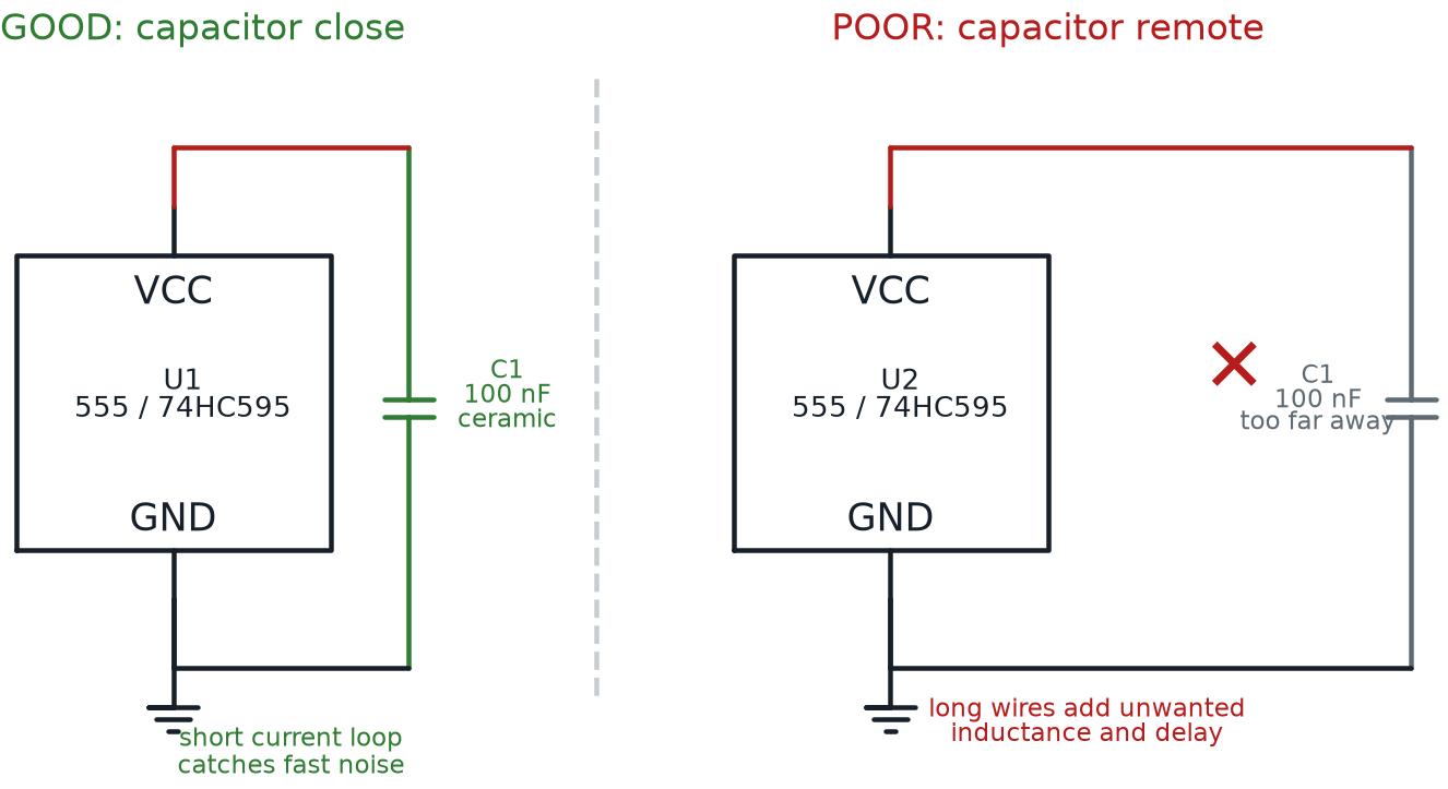
You won't wire a bypass capacitor into a project quite yet, but keep the name in your back pocket. Later chapters featuring integrated circuits — the 555 timer and the 74HC595 shift register — will call for exactly this small, unglamorous, essential part sitting right next to the chip's power pins.
Chapter Summary: Key Takeaways
You've now got the complete decoder for two of the most common parts in any electronics kit:
- The full resistor color code uses ten digit colors, a multiplier band, and a gold tolerance band or silver tolerance band to specify an exact value and how much it's allowed to drift
- A carbon film resistor and a metal film resistor are built from different materials but can share the same color code and the same quarter-watt resistor power rating, all wrapped in the same axial lead package
- A rheostat uses two terminals of a variable resistor to add resistance directly in series, while an NTC thermistor is the common type whose resistance falls as temperature rises
- The capacitor symbol shows whether a capacitor cares about polarity, and most small capacitors arrive in a radial lead package standing upright
- The capacitor value code decodes a 3-digit printed number into picofarads, using the same digit-and-multiplier trick as a resistor's bands, and that value converts cleanly between the picofarad, nanofarad, and microfarad units
- A capacitor voltage rating and a capacitor tolerance appear right alongside the value code, setting safe limits just like a resistor's tolerance band
- The capacitor dielectric defines a capacitor's family, from ceramic to electrolytic to the compact, precise tantalum capacitor — and a non-polarized capacitor like a ceramic disc never needs a polarity check at all
- A bypass capacitor is a small, unglamorous part with a big job: keeping power steady for the chips you'll meet soon
Chapter 12 zooms in on one part this chapter only mentioned in passing: the diode family. You'll meet rectifier diodes and Zener diodes, learn to read a diode's band marking, and explore how different LED colors, lenses, and viewing angles change the way light comes out.
Decoder Rings: Complete
 Fantastic work, builder — you can now decode any resistor's color bands and any capacitor's printed code on sight, no guessing required. That's a real engineer's superpower, and it'll save you time in every project from here on out. Current's flowing your way — see you in Chapter 12!