Series, Parallel, and Circuit Topology
Summary
Students explore how resistances combine in series and parallel, voltage references, current dividers, and the vocabulary of circuit topology (nodes, loops, branches). This chapter sets up the math-light intuition needed for the voltage-divider circuits used throughout the passive-components chapters.
Concepts Covered
This chapter covers the following 19 concepts from the learning graph:
- Parallel Resistance
- Equivalent Resistance
- Voltage Reference
- Series-Parallel Circuit
- Current Divider
- Circuit Topology
- Circuit Branch
- Electrical Energy
- Joule
- Watt-Hour
- Water Pipe Analogy
- Electric Field
- Insulator
- Conductor
- Semiconductor Material
- Static Electricity
- Electromotive Force
- Internal Resistance
- Terminal Voltage
Prerequisites
This chapter builds on concepts from:
- 1. Electricity Basics: Voltage, Current, and Resistance
- 2. Current, Charge, Units, and Electrical Safety
- 3. Circuit Analysis, Kirchhoff's Laws, and Energy
Chapter 3 ended with a single, tidy loop: one battery, resistors wired one after another, one loop current flowing through all of them. Real circuits are almost never that simple. The moment you plug two LEDs into the same breadboard power rail, or wire a sensor next to a motor, you've built something with more than one path for current to choose from. This chapter gives you the tools to handle that — and to talk about any circuit's wiring pattern with confidence, no matter how tangled it looks at first glance.
Time to Branch Out
 Welcome back, builder! Chapter 3 handed you the math for a single-path circuit. This chapter adds the missing piece: what happens the instant current gets a choice of paths. We'll cover parallel resistance, series-parallel combinations, the map-reading vocabulary engineers use for any circuit's layout, and — because every circuit is built out of something — a quick tour of the materials that make electricity possible in the first place. Let's light it up!
Parallel Resistance: When Current Gets a Choice
In a series circuit, current has exactly one route, so every resistor along that route fights the flow together, and resistances simply add. A parallel resistance is different: it describes what happens when two or more resistors are connected side by side across the same two nodes, giving current more than one route to choose between at once. Water finds this idea intuitive — if a river splits around an island into two channels, more total water can get past that island than if it only had one narrow channel to squeeze through.
That's exactly why adding a resistor in parallel always makes the combined resistance go down, never up — a fact that trips up almost every beginner the first time they meet it. Adding another resistor in series always slows the flow down further. Adding another resistor in parallel opens up another lane, so the flow finds it easier to get through overall.
The equivalent resistance of any network of resistors is the single resistor value that could replace the whole network without changing the current the battery delivers. You already calculated an equivalent resistance in Chapter 3, without the fancy name: when three resistors were wired in series, you added them up to find the total series resistance the loop "feels." Parallel resistors get their own version of that same idea, using a different formula.
Parallel Resistance Formula
where:
- \( R_{eq} \) is the equivalent resistance of the whole parallel combination, in ohms
- \( R_1, R_2, R_3 \) are the individual resistor values in each parallel branch, in ohms
For just two resistors — the case you'll meet constantly on a breadboard — there's a shortcut version of the same formula that skips the reciprocals:
Two-Resistor Parallel Shortcut
where:
- \( R_{eq} \) is the equivalent resistance of the two-resistor pair, in ohms
- \( R_1 \) and \( R_2 \) are the two resistor values, in ohms
Try it with real numbers: a 100 Ω resistor and a 300 Ω resistor wired in parallel combine to \( R_{eq} = \dfrac{100 \times 300}{100 + 300} = \dfrac{30{,}000}{400} = 75 \) Ω — a smaller number than either original resistor. That's the pattern to remember: a parallel combination is always smaller than its smallest branch.
Here's how series and parallel resistance compare side by side:
| Circuit Type | Equivalent Resistance Formula | What Happens as You Add More Resistors |
|---|---|---|
| Series | \( R_{eq} = R_1 + R_2 + R_3 + \dots \) | Total resistance always goes up |
| Parallel | \( \dfrac{1}{R_{eq}} = \dfrac{1}{R_1} + \dfrac{1}{R_2} + \dfrac{1}{R_3} + \dots \) | Total resistance always goes down |
The Backwards-Feeling Rule
 I know, I know — "add a resistor and get less resistance" sounds backwards the first time you hear it. Picture toll booths on a highway instead of one pipe: adding a second booth doesn't slow traffic down, it opens up another lane. More parallel paths, less overall resistance to the flow. Once that clicks, you'll never forget it.
Series-Parallel Circuits: Mixing Both Patterns
Most real circuits — including plenty you'll build later in this course — aren't purely series or purely parallel. They're a series-parallel circuit: a circuit that combines both wiring patterns in the same network, some components chained one after another and others branching side by side. Solving one looks intimidating at first, but the trick is simple: find any parallel section, collapse it down into its single equivalent resistance, and then treat the whole thing as one ordinary series chain.
Let's reuse the three resistors from Chapter 3's worked example — 100 Ω, 220 Ω, and 330 Ω — but rewire them. Instead of one long chain, put the 220 Ω and 330 Ω resistors side by side in parallel, then wire that parallel pair in series with the 100 Ω resistor and a 9-volt battery. First, collapse the parallel pair: \( R_{eq} = \dfrac{220 \times 330}{220 + 330} = \dfrac{72{,}600}{550} = 132 \) Ω. Now it's just a two-resistor series chain: \( R_{total} = 100 + 132 = 232 \) Ω. Ohm's Law finishes the job: \( I = V \div R = 9 \div 232 \approx 0.0388 \) amps, or about 38.8 mA flowing out of the battery.
The interactive simulation below lets you build both simple patterns side by side and watch exactly how current and voltage behave differently in each one.
Diagram: Series and Parallel Circuits Comparison
Run the Series and Parallel Circuits Comparison fullscreen
Series and Parallel Circuits Comparison (reused MicroSim)
Type: microsim
sim-id: series-parallel
Library: p5.js
Status: Reused
Source: https://dmccreary.github.io/intro-to-physics-course/sims/series-parallel/
Source Repo: https://github.com/dmccreary/intro-to-physics-course/tree/main/docs/sims/series-parallel
Reused from the MicroSim catalog (WHAT match score 0.7829). Bloom Taxonomy: Apply (L3). Bloom Verb: calculate. Learning objective: Calculate the equivalent resistance of a series circuit and a parallel circuit side by side, and predict how current and voltage divide differently in each, by adjusting resistor values and observing which bulb glows brightest in an animated comparison.
Collapse, Then Conquer
 Whenever a circuit looks like a tangle of series and parallel sections at once, don't panic — just work from the inside out. Collapse the smallest parallel group into one equivalent resistor first, then treat the result as a plain series chain. Repeat as needed. Even complicated-looking circuits fall apart into simple steps this way.
Current Dividers and Voltage References
Chapter 2 taught you that a series circuit divides voltage among its components — that's voltage division. A parallel circuit has a mirror-image trick: it divides current instead. A current divider splits a single incoming current across two or more parallel branches, sending more current down the branch with less resistance and less current down the branch with more resistance.
Diagram: Two-Branch Current Divider
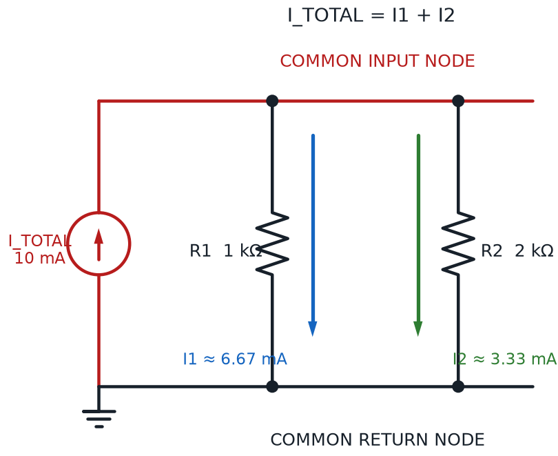
Current Divider Formula (Two Branches)
where:
- \( I_1 \) is the current flowing through branch 1, in amps
- \( I_{total} \) is the total current arriving at the junction, in amps
- \( R_1 \) is the resistance of branch 1, and \( R_2 \) is the resistance of the other branch, both in ohms
Notice the branch with the smaller resistance value shows up as the larger fraction — current always prefers the easier path, just like Chapter 3's junction rule (Kirchhoff's Current Law) demands. Going back to the 100 Ω and 300 Ω parallel pair from earlier: if that 75 Ω combination carries a total of 120 mA fed by a 9-volt source, the current divider formula gives 90 mA through the 100 Ω branch and 30 mA through the 300 Ω branch — and \( 90 + 30 = 120 \) mA, exactly matching the total, just as Kirchhoff's Current Law promises.
Watch the Flipped Fraction
 The single most common current-divider mistake: putting the wrong resistor on top of the fraction. To find the current through branch 1, the formula uses \( R_2 \) — the other branch's resistance — in the numerator, not \( R_1 \). Double-check which resistor you're solving for before you plug in numbers.
Every one of these voltage and current calculations is measured relative to something — you can't just say "this point is at 5 volts" without agreeing on a starting line. That starting line is called a voltage reference: a fixed point in a circuit that every other voltage gets compared against. Chapter 1 already introduced the most common choice of voltage reference, ground, but technically any node in a circuit could be chosen as the zero-volt reference point — ground is simply the overwhelmingly popular convention, because it usually lines up with a battery's negative terminal.
Circuit Topology: Reading the Map, Not Just the Board
Two circuits can look completely different laid out on a breadboard — one squeezed into a corner, one spread across the whole board — and still be electrically identical underneath. What matters isn't where the wires physically sit, but how the components connect. That underlying connection pattern is called circuit topology: the map of nodes, branches, and loops that describes a circuit's wiring, independent of its physical layout.
Three vocabulary words make that map precise:
- A node (introduced in Chapter 3) is any point in a circuit where two or more components connect
- A circuit branch is a single path between two nodes, containing one or more components wired in series along that path
- A loop is any closed path through a circuit that starts and ends at the same node without repeating a branch
Here's a detail that surprises a lot of beginners: two points that look far apart on your physical breadboard can be the same electrical node, because the breadboard's hidden metal strips connect entire rows together internally. Topology is about that hidden, electrical reality — not about how far apart two holes look on the plastic.
Explore the circuit below to see nodes, branches, and loops highlighted directly on a series-parallel circuit diagram.
Diagram: Circuit Topology Explorer
Circuit Topology Explorer
Type: diagram
sim-id: circuit-topology-explorer
Library: p5.js
Status: Specified
Purpose: Help students recognize and label nodes, branches, and loops on a real series-parallel circuit diagram, and see that topology describes electrical connection, not physical position.
Bloom Taxonomy: Remember (L1). Bloom Verb: identify.
Learning objective: Identify the nodes, branches, and loops in a series-parallel circuit (one battery, one series resistor, and two parallel resistors) by clicking each part of the diagram and reading its definition in an infobox.
Canvas layout: - Left/center (roughly 70% of width): a series-parallel circuit diagram — a battery, one resistor in series, then two resistors in parallel, forming a closed loop — with four labeled node dots (A, B, C, D) - Right side (roughly 30%, stacking below on narrow screens): an infobox panel showing information about whichever element was last clicked
Visual elements: - Four node dots, drawn as filled circles at every junction point, each labeled A–D - Three branches, drawn as distinct colored line segments: the series-resistor branch, and the two parallel-resistor branches - A toggle-highlighted loop overlay that traces one full loop around the circuit when the "Loop" button is active - A small "same node!" pulse effect that flashes both ends of a node whenever a node with multiple visual connection points is clicked, reinforcing that spread-out points can share one electrical identity
Interactive controls: - Click any node dot to open an infobox defining "node" and confirming how many branches meet there - Click any branch to open an infobox defining "circuit branch" and listing which components lie along it - Button: "Highlight a Loop" traces one closed loop in a pulsing outline and opens an infobox defining "loop" - Button: "Reset View" clears all highlights and infobox content
Default parameters: - No element pre-selected; infobox shows a "Click a node, a branch, or the Loop button to explore this circuit's topology" placeholder
Behavior when an element is clicked: - Node: infobox shows "Node — a connection point where two or more components meet. This node connects N branches." (N calculated from the actual diagram) - Branch: infobox shows "Circuit Branch — a single path between two nodes. This branch contains: [component list]." - Loop button: infobox shows "Loop — a closed path that returns to its starting node without reusing a branch. This circuit has more than one possible loop!"
Data Visibility Requirements: Stage 1 (default): Show the full series-parallel diagram with all four nodes and three branches visible but unselected Stage 2 (node or branch clicked): Show the selected element highlighted in the diagram plus its matching infobox definition Stage 3 (Highlight a Loop clicked): Show one complete loop traced in an animated outline, so "loop" becomes a visible path rather than an abstract word
Instructional Rationale: This is a Remember-level objective (identify and label topology vocabulary), so the interaction is a straightforward click-to-reveal labeling pattern rather than a calculation tool — matching how a beginner actually learns new vocabulary: point at something, learn its name, repeat.
Color scheme: Blue circuit lines and node dots on a light background, with the currently selected element highlighted in warm orange, consistent with the color logic used throughout this book.
Responsive behavior: The diagram and infobox panel reflow into a stacked layout on narrow screens; all nodes, branches, and buttons remain clickable at any window width.
Implementation: p5.js, using clickable regions defined around each node and branch; infobox rendered as an HTML panel beside (or below, on narrow screens) the canvas.
New Vocabulary, Same Circuits
 Nodes, branches, and loops can feel like a lot of new words at once, but you already understand every circuit they describe — you built plenty of them in Chapter 3. This section just gives you the precise language engineers use, so when a datasheet or a teammate says "loop," you'll know exactly what they mean.
A Material World: Conductors, Insulators, and Semiconductors
Every circuit you've studied so far assumed wires just work — that electrons flow freely through them and stop dead at the plastic coating. That behavior isn't an accident; it comes straight from the material each part is made of. A conductor is a material that allows electric current to flow through it easily, because its atoms hold onto their outer electrons loosely, letting them drift from atom to atom with very little resistance. Copper, aluminum, and most metals are excellent conductors, which is exactly why they're used inside wires.
An insulator is the opposite: a material that strongly resists the flow of electric current, because its electrons are held tightly in place and simply won't drift. Rubber, glass, plastic, and wood are all insulators, which is why the coating around every wire in your kit is made of plastic — it keeps current safely contained inside the copper instead of leaking out to your fingers.
Between those two extremes sits one of the most important materials in modern electronics: semiconductor material. A semiconductor conducts current better than an insulator but worse than a true conductor on its own — and, more importantly, its conductivity can be controlled and switched on purpose. Silicon is by far the most common semiconductor material, and it's the substance hiding inside every transistor, every 555 timer, and every 74HC595 shift register in your kit. You'll learn exactly how transistors use this switchable behavior later in this course.
| Material Type | How Easily Current Flows | Everyday Examples |
|---|---|---|
| Conductor | Very easily — electrons drift almost freely | Copper wire, aluminum foil, most metals |
| Insulator | Barely at all — electrons stay locked in place | Rubber, glass, plastic, wood |
| Semiconductor Material | In between — and controllable on purpose | Silicon, germanium (inside every transistor and chip) |
Sort the everyday materials below into their correct category, and see immediately whether your guess was right.
Diagram: Material Conductivity Sorter
Material Conductivity Sorter
Type: microsim
sim-id: material-conductivity-sorter
Library: p5.js
Status: Specified
Purpose: Help students classify common, everyday materials as conductors, insulators, or semiconductor materials, reinforcing the comparison table with hands-on sorting practice.
Bloom Taxonomy: Understand (L2). Bloom Verb: classify.
Learning objective: Classify everyday materials — copper wire, aluminum foil, rubber, glass, plastic, wood, a silicon chip, pencil graphite, salt water, and a steel paperclip — as a conductor, insulator, or semiconductor material, by dragging each material card into the correct one of three labeled bins and receiving immediate right/wrong feedback.
Canvas layout: - Top strip: a horizontal row of draggable material cards, each showing an icon and a name - Bottom: three labeled drop bins side by side — "Conductor," "Insulator," "Semiconductor Material" — each with a distinct background color - Small score readout in the corner: "Correct: _ / 10"
Visual elements: - Ten material cards: copper wire, aluminum foil, rubber, glass, plastic, wood, silicon chip, pencil graphite, salt water, and steel paperclip - Each bin glows green briefly when a correct card is dropped in, and glows red with a gentle shake animation when an incorrect card is dropped in, then the card returns to the top row to try again - A small info icon on each card that, when hovered, shows a one-line reason for its correct classification
Interactive controls: - Drag-and-drop: move each material card into one of the three bins - Hover any card for a tooltip explaining why it belongs where it does (shown even before sorting, as an optional hint) - Button: "Reset" returns all cards to the top row and clears the score - Button: "Reveal All" (after at least one attempt) shows every card correctly sorted, for review
Default parameters: - All ten cards start in the top row, unsorted; score starts at 0/10
Data Visibility Requirements: Stage 1 (default): Show all ten unsorted cards and three empty bins Stage 2 (card dropped): Show immediate color feedback (green/red) plus the card's one-line explanation, and update the running score Stage 3 (Reveal All): Show the fully sorted board with every material in its correct bin, so learners can review any they missed
Instructional Rationale: This is an Understand-level classification objective, so the design uses a drag-and-drop sorter with immediate corrective feedback rather than a passive diagram. Sorting concrete, familiar objects (a paperclip, a pencil, a glass) builds the category boundaries faster than reading definitions alone, and the always-visible hint tooltip keeps the activity encouraging rather than purely a test.
Color scheme: Green bin highlight for conductor-friendly feedback, cool gray for insulator, warm orange for semiconductor material (echoing this book's accent color for anything related to switching or control), on a light neutral background.
Responsive behavior: The three bins stack vertically on narrow screens with the card row scrolling horizontally above them; drag-and-drop gestures work with touch as well as mouse.
Implementation: p5.js, with each material card as a draggable object checked against a lookup table of correct bins on drop; bins rendered as fixed drop-target regions.
Electric Fields and Static Electricity
Zoom in past the level of wires and resistors, and there's a deeper reason voltage pushes current at all: electric charge creates an invisible push-and-pull all around it, called an electric field. Every charged object — an electron, a battery terminal, even your own body after shuffling across a carpet — is surrounded by this field, and any other charge sitting inside that field feels a force from it. Voltage, the "push" you met all the way back in Chapter 1, is really just a way of measuring how strong that electric field's push is between two points.
Most of the time, charge moves — that's current, the whole subject of this course. But charge can also sit still and simply build up in one place, especially on materials that don't conduct it away easily. That buildup of charge, with nowhere to flow, is called static electricity. Chapter 3 already mentioned one consequence of static electricity — a static discharge that can silently damage a sensitive chip — but the buildup itself shows up in plenty of everyday, harmless ways too:
- Rubbing a balloon on your hair and watching strands stand up, pulled by the balloon's electric field
- A sock clinging to a shirt straight out of the dryer
- A small spark and snap when you touch a metal doorknob after walking across a carpet in dry weather
- Lightning itself — an enormous static discharge between a storm cloud and the ground
Static electricity is really just an electric field with nowhere convenient to send its charge — the instant a conductor offers a path (a finger near a doorknob, a wire touching a chip), that stored-up charge finds it and discharges all at once.
Same Idea, Bigger and Smaller Scale
A doorknob spark and a lightning bolt are the exact same phenomenon at wildly different scales — that's shockingly satisfying once you notice it. Both are just built-up charge finally finding a conductor to jump through.
Storing and Spending Electrical Energy
Power told you how fast a circuit does work, measured in watts — but it never told you the total amount of work done over time. That total is called electrical energy: the overall amount of electrical work a circuit performs, found by multiplying power by the time it acts.
Electrical Energy
where:
- \( E \) is electrical energy, measured in joules (J) when power is in watts and time is in seconds
- \( P \) is power, measured in watts (W)
- \( t \) is time, measured in seconds (s)
When power is measured in watts and time in seconds, the energy comes out in an official unit called the joule (J), named after physicist James Joule — one joule is a genuinely tiny amount of energy, roughly what it takes to lift a small apple one meter off a table. A single AA battery powering an LED for an hour releases only a few dozen joules, which is why joules are the natural unit for a single instant of circuit behavior, but an awkward one for describing how long a battery lasts.
Tiny Unit, Huge Job
A single joule doesn't sound like much, and it isn't — but that's exactly why it's the right-sized unit for a single instant of circuit behavior. Zoom out to a whole afternoon of use, though, and joules pile up fast, which is exactly the problem the next unit solves.
For longer stretches of time, electronics uses a more convenient, practical unit: the watt-hour (Wh) — the amount of energy used by something drawing one watt of power for one full hour. A battery's printed capacity (often given in milliamp-hours) is really just a shorthand way of expressing how many watt-hours of energy it can deliver before running dry.
Go all the way back to Chapter 1's water pipe analogy for one last comparison: if power is how fast water flows through a pipe right now, electrical energy is the total volume of water that ends up in a bucket after the tap has been running for a while. A wide-open tap (high power) fills the bucket fast; leave a narrow trickle running for hours (lower power, longer time) and you can end up with the exact same total volume — the exact same energy — in the bucket either way.
Batteries in the Real World: EMF, Internal Resistance, and Terminal Voltage
Every battery so far in this course has been treated as a perfect, unwavering source of voltage. Real batteries aren't quite that perfect, and the vocabulary in this final section explains why a battery's voltage sags a little whenever it's actually put to work.
The voltage a battery would supply if it had absolutely nothing inside fighting the flow is called its electromotive force (often abbreviated EMF, and written with the Greek letter \( \varepsilon \)) — the ideal, ceiling-level push the battery's chemistry is capable of producing. But every real battery also has a tiny bit of resistance built into its own internal chemistry and construction, called its internal resistance, which quietly eats into that push the instant current starts flowing.
That leftover, usable voltage — the voltage you'd actually measure with a meter across the battery's real terminals while current is flowing — is called the terminal voltage, and it's always a little lower than the EMF once a circuit is drawing current.
Diagram: Battery EMF and Internal Resistance Model
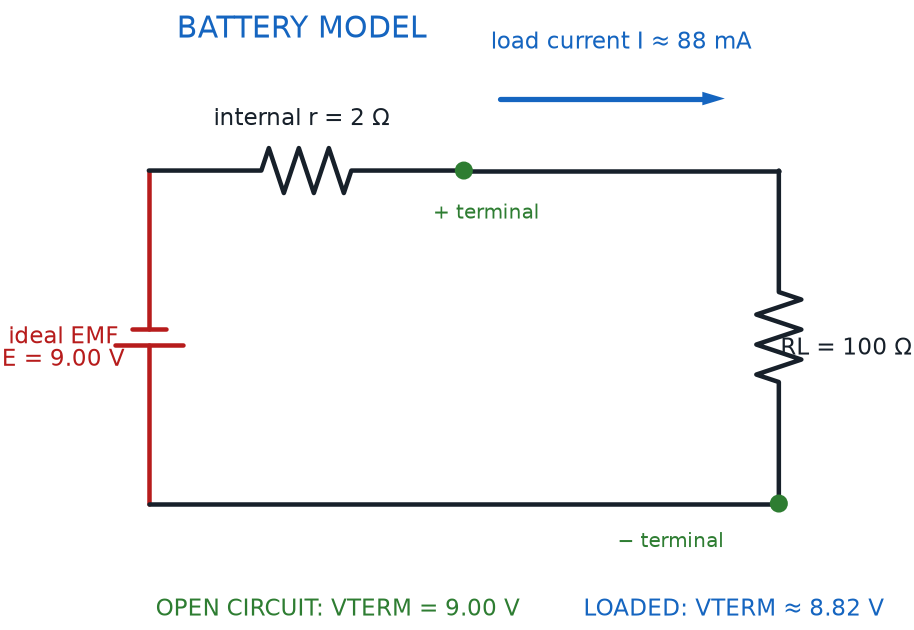
Terminal Voltage
where:
- \( V_{terminal} \) is the terminal voltage, measured in volts (V)
- \( \varepsilon \) is the battery's electromotive force (EMF), measured in volts (V)
- \( I \) is the current the battery is supplying, measured in amps (A)
- \( r_{internal} \) is the battery's internal resistance, measured in ohms (Ω)
This is exactly why a battery pack can measure a healthy voltage with a meter when nothing is connected, then sag noticeably the moment a power-hungry motor switches on: more current flowing means more voltage lost across that small internal resistance. A gently used AA battery has only a tiny internal resistance, so the sag is barely noticeable in most of this course's projects — but it grows as a battery ages, which is one more reason a "dead" battery struggles the most exactly when a circuit asks it for the most current.
A Little Sag Is Normal
If you ever measure a battery's voltage and get a slightly different number once a motor or a bright LED is actually running, don't worry — that's terminal voltage doing exactly what it's supposed to do. It's not a broken battery or a mistake in your circuit; it's just internal resistance quietly doing its job.
Chapter Summary: Key Takeaways
You now have the full toolkit for reading, describing, and calculating any circuit's wiring pattern, no matter how tangled it looks:
- Parallel resistance always makes the combined equivalent resistance smaller, the opposite of what adding resistors in series does
- A series-parallel circuit combines both patterns; solve it by collapsing each parallel section into its equivalent resistance, then treating the result as a series chain
- A current divider splits current across parallel branches, sending more current down the lower-resistance path; a voltage reference is the fixed point every other voltage in a circuit is measured against
- Circuit topology — the map of nodes, circuit branches, and loops — describes how a circuit connects electrically, independent of its physical layout on a breadboard
- Conductors (like copper) let current flow easily, insulators (like plastic) resist it almost completely, and semiconductor material (like silicon) sits in between and can be switched on purpose
- Every charge is surrounded by an electric field; when charge builds up with nowhere to flow, that's static electricity
- Electrical energy (\( E = P \times t \)) is measured in joules for small, instant amounts and watt-hours for practical, everyday amounts — just like the total volume filling a bucket in the water pipe analogy
- A battery's electromotive force is its ideal push; its internal resistance quietly reduces that push under load, leaving a slightly lower terminal voltage at the battery's actual terminals
That's a serious circuit-analysis toolkit — parallel math, topology vocabulary, materials science, and real-battery behavior, all in one chapter.
Every Path Accounted For
 Nice wiring, builder! You just unlocked the power to solve any series-parallel circuit, name every node and branch like a pro, and explain what's really happening inside a battery under load. Grab your kit — Chapter 5 is where these ideas start meeting real components. Current's flowing your way!