Diodes and LEDs
Summary
This chapter covers diode behavior — forward and reverse bias, rectifier and Zener diodes — and the electrical characteristics of LEDs (forward voltage, current rating, polarity) that set up every LED circuit built in the Output Components chapters.
Concepts Covered
This chapter covers the following 18 concepts from the learning graph:
- Diode Symbol
- Diode Band Marking
- Rectifier Diode
- Zener Diode
- Flyback Diode
- Diode Forward Bias
- Diode Reverse Bias
- Diode Current Rating
- Red LED
- Green LED
- Blue LED
- LED Viewing Angle
- LED Lens Shape
- LED Lifespan
- Potentiometer Wiper
- Linear Taper
- Logarithmic Taper
- Trim Pot Adjustment Screw
Prerequisites
This chapter builds on concepts from:
- 1. Electricity Basics: Voltage, Current, and Resistance
- 2. Current, Charge, Units, and Electrical Safety
- 5. Conductors, Batteries, and Circuit Vocabulary Review
- 9. Resistors and Capacitors
- 10. Capacitor Timing and Resistor Values
Chapter 10 handed you the diode's basics — one-way current flow, anode, cathode, and the forward voltage that makes an LED glow. That was just enough to wire a single LED safely. This chapter goes much deeper into what actually makes a diode a diode, and what happens inside an LED before its light ever reaches your eyes.
You'll learn to read the little painted band on a diode's body, the same way Chapter 11 taught you to read a resistor's color stripes. You'll meet three specialized diode types that each do a different job in real circuits: the rectifier diode, the Zener diode, and the flyback diode. And you'll find out exactly why a red LED, a green LED, and a blue LED each need a slightly different resistor, even in the exact same circuit.
Before the chapter closes, you'll circle back to a part you already know — the potentiometer — and finish the story Chapter 9 started. What's actually happening inside that little dial when you turn it? That's this chapter's last stop.
Diving Deeper Into Diodes
 Welcome back, builder! Chapter 10 gave you the diode's greatest hits — today we're going deep on the full album: diode types, bias directions, LED colors, and the whole story behind that potentiometer dial. Let's light it up!
Reading a Diode: Symbol and Band Marking
Every diode in a circuit diagram uses the exact same schematic shape, no matter what job it's doing. The diode symbol is a triangle pointing toward a straight bar, where the triangle's point represents the anode side and the bar represents the cathode side — current is only allowed to flow in the direction the triangle points, straight into that bar. It's a picture of the one-way-valve idea from Chapter 10, drawn as an arrow hitting a wall.
Physical diodes need a way to show which end is which without printing a whole schematic on a tiny cylindrical body. The diode band marking is a single painted stripe near one end of a diode's body that marks the cathode lead, matching the bar in the schematic symbol. Look for that stripe the same way you looked for an LED's flat edge or shorter lead in Chapter 10 — it's the fastest way to orient a plain diode correctly before plugging it into a breadboard.
Reading a diode takes three quick checks, in order:
- Find the painted band near one end of the diode's body
- Match that band to the bar in the schematic symbol — the banded end is the cathode
- Point the opposite, unmarked end toward the anode side of your circuit
One Symbol, Every Diode
 Here's the shortcut worth remembering: triangle-into-bar always means anode-into-cathode, on every diode symbol you'll ever see — rectifier, Zener, flyback, or LED. Learn this one shape once, and you can read any diode's orientation in any schematic for the rest of your electronics life.
Three Jobs, Three Diode Types
Not every diode does the same job. This course's kit sticks to LEDs, but understanding three specialized diode types — quietly at work inside gadgets you already own — makes you a much sharper circuit reader.
A rectifier diode is a diode designed to convert alternating current (AC) into direct current (DC) by blocking current during the reverse half of every AC cycle and letting only the forward half through. Nearly every phone charger and USB power adapter in your house uses rectifier diodes to turn the AC power from a wall outlet into the steady DC voltage your electronics actually need. This course never builds an AC circuit — that's outside its safe, low-voltage scope — but knowing a rectifier diode's job helps you recognize why almost every powered gadget has a few of them hidden inside.
A Zener diode is a diode specifically designed to conduct current in the reverse direction once a precise voltage is reached, holding that voltage steady across itself instead of simply blocking current the way a rectifier diode does. Picture a pressure relief valve that stays shut until the pressure hits a set point, then opens just enough to hold the pressure steady right there — that's a Zener diode, holding a circuit's voltage at a safe, predictable level.
A flyback diode is a diode wired backward across a motor, relay, or other coil-based part, added to safely absorb the voltage spike created when current through that coil is suddenly switched off. This course's kit includes DC motors, and every one of them can produce that kind of spike. A flyback diode sits reverse-biased — blocking, doing nothing at all — the entire time the motor spins normally. The instant the motor switches off, its collapsing magnetic field tries to push current backward through the circuit, and the flyback diode gives that surge a safe path instead of letting it fry a nearby transistor or switch.
Diagram: Rectifier, Flyback, and Zener Diode Circuits
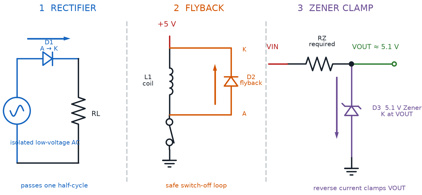
The table below lines up all three types side by side.
| Diode Type | Normal Job | Conducts When | Common Location |
|---|---|---|---|
| Rectifier Diode | Converts AC to DC | Forward-biased, every half cycle | Phone chargers, power adapters |
| Zener Diode | Holds a steady voltage | Reverse-biased, at its rated voltage | Voltage-regulator circuits |
| Flyback Diode | Protects against motor voltage spikes | Reverse-biased normally; conducts briefly the instant the motor switches off | Circuits with motors, relays, or coils |
Keep this table in mind — the sim later in this chapter lets you flip a diode's bias direction and watch current respond in real time.
Forward Bias and Reverse Bias in Action
Chapter 10 explained that a diode only conducts one way, but it never gave that behavior a name. Now it does.
Diode forward bias is the condition where voltage is applied in a diode's allowed direction — positive toward the anode, negative toward the cathode — letting current flow once the voltage passes the diode's forward voltage. This is the normal, everyday state for every diode and LED you've wired so far in this course. Current flows, and for an LED, light appears.
Diode reverse bias is the condition where voltage is applied backward — positive toward the cathode, negative toward the anode — which the diode blocks, allowing essentially no current through. At this course's safe, low voltages, a reverse-biased LED or diode simply stays dark or inactive; nothing gets damaged, and nothing gets hot. That calm blocking behavior is exactly what makes a flyback diode useful — it sits reverse-biased and harmless until the exact moment it's needed.
Flip the bias direction yourself and watch current respond in the sim below.
Diagram: Forward vs. Reverse Bias Breadboard Demo
Forward vs. Reverse Bias Breadboard Demo
Type: microsim
sim-id: diode-forward-reverse-bias-demo
Library: p5.js
Status: Specified
Purpose: Let students flip a battery's orientation on a rendered breadboard circuit and directly observe current flowing (forward bias, indicator LED lit) versus current being blocked (reverse bias, indicator dark), then push current past the diode's current rating to see why the rating matters.
Bloom Taxonomy: Understand (L2) / Apply (L3). Bloom Verb: demonstrate, predict.
Learning objective: Given a rendered breadboard circuit with a diode, a battery, and an LED current indicator, predict and observe whether current flows when the diode is forward-biased versus reverse-biased, and observe what happens as forward current approaches and exceeds the diode's current rating.
Reuse check: An embeddings search (find-similar-templates, mode=reuse) for "Title: Forward vs Reverse Bias Diode Breadboard Demo | Topic: Diode forward bias and reverse bias, current flow through a diode on a breadboard, diode current rating | Subjects: Electronics, Beginning Electronics | Grade Level: Junior High | Learning Objectives: Demonstrate how current flows through a forward-biased diode and is blocked by a reverse-biased diode on a breadboard circuit" returned a top match of "Breadboard" (dmccreary/microsims, WHAT score 0.5246, recommendation "generate") — below the 0.60 template threshold, though it is the closest structural match. The second match, "P-N Junction Voltage Explorer" (0.4908), is undergraduate-level depletion-region physics and out of scope. This is a new specification, and a strong candidate for the breadboard-sim-generator skill: this repository's existing button-led-breadboard and light-dark-detector sims already share a breadboard-lib.js rendering library with real tie-point positions and animated current flow that this sim can extend directly with a diode component and bias-direction logic.
Canvas layout: Main area shows a rendered half breadboard with a battery pack, a diode (band clearly visible), and a series LED current indicator; right side panel holds a "Flip Battery" button, a current-source slider (0-30 mA), and an infobox.
Components/elements involved: A rendered breadboard with power and ground rails; a battery pack with a visible polarity marking; a diode with a rendered band marking; a series LED that lights when current flows; connecting wires; an animated current-flow indicator along the wires.
Required interactivity: - Clicking "Flip Battery" reverses the battery's polarity, toggling the diode between forward and reverse bias; forward bias animates current flow and lights the indicator LED, while reverse bias halts the animation and the infobox explains that the diode is blocking current with no damage at this course's low voltage - Dragging the current-source slider raises the simulated source current; below the diode's current rating the indicator brightens normally, and past the rating a warning flash appears and the infobox explains the overheating risk, without actually damaging the simulated part - Hovering the diode opens an infobox stating the current bias condition and the diode's current rating - Button "Reset" returns to the default forward-biased, low-current state
Default state: Battery oriented for forward bias, current slider at 15 mA, indicator LED lit at normal brightness, infobox reads "Forward biased — current flows from anode to cathode, well under the rating."
Data Visibility Requirements: Stage 1: Show the battery's current polarity orientation Stage 2: Show the resulting bias condition label ("Forward Biased" or "Reverse Biased") Stage 3: Show the animated current flow, or its absence, along the wires Stage 4: Show the current-source value next to the diode's current rating for direct comparison
Instructional Rationale: An Understand/Apply "demonstrate/predict" objective calls for a manipulable breadboard simulation with concrete before-and-after states for each bias direction and current level, so students connect the abstract bias vocabulary to a visible, testable outcome rather than an animation they only watch.
Color scheme: Green current-flow dots and a lit indicator LED for forward bias, gray and dim for reverse bias, red warning flash when current exceeds the diode's rating, consistent with the palette used in this chapter's other diagrams.
Responsive behavior: Breadboard view and the control/infobox panel stack vertically on narrow screens; the current slider and Flip Battery button remain full-width and touch-friendly.
Implementation: p5.js, built using the breadboard-sim-generator skill's rendered tie-point approach, extending this repository's existing breadboard-lib.js (already used in button-led-breadboard and light-dark-detector) with a diode component and bias-direction logic.
Every diode also has a limit to how much current it can safely carry. The diode current rating is the maximum forward current a diode can conduct continuously without overheating and failing, listed on its datasheet — often around 1 amp for a general-purpose rectifier diode, far more than the roughly 20 milliamps a standard LED can handle. Push a diode past its current rating and heat builds up faster than the part can shed it, exactly the failure the slider in the sim above is designed to let you see safely.
Ratings Aren't Suggestions
 A diode blocking reverse current feels perfectly safe, and at this course's voltages, it is. But push any diode's reverse voltage or forward current past its rating, and that safety margin disappears fast. Always check a diode's current rating before wiring it in — the exact same habit Chapter 10 taught you for LEDs.
LED Colors and Their Forward Voltages
Chapter 10 gave you one forward voltage number for LEDs in general, close to 2 volts. The real story is more colorful — literally. Different LED colors are built from different semiconductor materials, and each material has its own natural forward voltage.
A red LED is an LED with a forward voltage typically around 1.8 to 2.2 volts, the lowest of the common colors and the reason red LEDs were the first widely available LED color decades ago. A green LED is an LED with a forward voltage typically around 2.0 to 3.2 volts depending on its exact shade, since "green" covers a wider range of underlying materials than red or blue. A blue LED is an LED with a forward voltage typically around 2.8 to 3.4 volts, the highest of the three primary colors — a direct result of the different, harder-to-manufacture semiconductor material blue LEDs are built from.
| LED Color | Typical Forward Voltage | Semiconductor Family |
|---|---|---|
| Red LED | 1.8 - 2.2 V | Aluminum gallium arsenide and similar |
| Green LED | 2.0 - 3.2 V | Gallium phosphide or indium gallium nitride |
| Blue LED | 2.8 - 3.4 V | Indium gallium nitride |
Because forward voltage changes by color, the current-limiting resistor equation from Chapter 10 gives a different answer for every color, even at the exact same supply voltage and target current. Swap a red LED for a blue LED without changing the resistor, and the blue LED runs at a much lower current — sometimes dim, sometimes not lighting at all.
Try the math yourself: a 5-volt supply, a blue LED with a 3.2-volt forward voltage, and a target current of 0.015 amps gives \( R = \frac{5 - 3.2}{0.015} = 120 \) ohms — a noticeably smaller resistor than the 220 ohms Chapter 10 calculated for a red LED under the same conditions.
Same Formula, New Number
 Whenever you swap an LED's color mid-project, plug that color's own forward voltage back into Chapter 10's resistor equation before you power it up. It only takes a few seconds, and it's the difference between a bright, safe LED and a dim, underpowered one.
Shaping the Light: Viewing Angle, Lens Shape, and Lifespan
An LED's forward voltage decides how much light it can produce, but two more factors decide where that light actually goes.
LED viewing angle is the width of the cone of light an LED produces, measured in degrees, describing how spread out or focused its light appears. A narrow viewing angle, like 20 degrees, concentrates light into a tight, spotlight-like beam. A wide viewing angle, like 100 degrees or more, spreads that same light across a much broader area, more like a floodlight.
Viewing angle isn't random — it's built directly into the part. LED lens shape is the shape of the clear or frosted plastic dome covering an LED's semiconductor chip, which bends the light on its way out and directly sets the LED's viewing angle. A tall, rounded dome lens works like a tiny lens, narrowing the beam into a focused cone. A flatter, more diffused lens scatters light more evenly, widening the viewing angle at the cost of a less intense beam straight ahead.
Compare colors, lens shapes, and the beams they produce in the sim below.
Diagram: LED Color, Viewing Angle, and Lens Shape Explorer
LED Color, Viewing Angle, and Lens Shape Explorer
Type: microsim
sim-id: led-color-viewing-angle-explorer
Library: p5.js
Status: Specified
Purpose: Let students compare forward voltage across red, green, and blue LEDs, and see how switching between a rounded-dome lens and a flat, diffused lens changes an LED's viewing angle.
Bloom Taxonomy: Understand (L2). Bloom Verb: compare, explain.
Learning objective: Compare forward voltage across red, green, and blue LEDs using a live bar chart, and explain how a rounded dome lens versus a flat, diffused lens changes an LED's viewing angle.
Reuse check: An embeddings search (find-similar-templates, mode=reuse) for "Title: LED Color Forward Voltage and Viewing Angle Explorer | Topic: Red green and blue LED forward voltage comparison, LED viewing angle cone, LED lens shape effect on light spread | Subjects: Electronics, Beginning Electronics | Grade Level: Junior High | Learning Objectives: Compare forward voltage across red green and blue LEDs and explain how lens shape changes an LED's viewing angle" returned three matches, all below the 0.60 template threshold: "Brightness Envelopes for Advanced Patterns" (0.5652, Chart.js, moving-rainbow repo), "HSV Color Space Explorer" (0.5549), and "LED Nightlight Circuit" (0.5382) — all built around LED animation effects or color theory rather than forward-voltage or lens-shape comparisons. A keyword grep of the 3,764-entry catalog for "led color," "forward voltage," and "viewing angle" returned zero hits. This is a new specification. Per this course's MicroSim guidance, a breadboard-based rendering was also considered for this concept, but a side-by-side comparison chart better serves the compare/explain objective than a single wired LED circuit would.
Canvas layout: Left side shows a rendered LED with an adjustable lens-shape toggle and an animated light-cone graphic showing beam spread; right side holds a color selector (red/green/blue), a live forward-voltage readout, a small bar chart comparing all three colors' forward voltages, and an infobox.
Components/elements involved: A rendered LED with a swappable lens shape (rounded dome or flat/diffused); an animated light-cone graphic whose spread angle changes with lens shape; a three-color selector; a bar chart of forward voltage by color; a viewing-angle readout in degrees.
Required interactivity: - Selecting a color (red, green, or blue) updates the rendered LED's glow color, the forward-voltage readout, and the highlighted bar on the chart - Toggling lens shape between rounded dome and flat/diffused animates the light cone narrowing to about 20-30 degrees or widening to 100 degrees or more, with the angle readout updating live - Hovering any bar on the chart shows that color's exact forward-voltage range - Hovering the light cone opens an infobox stating the LED viewing angle definition - Button "Reset" returns to the default state
Default state: Red LED selected, rounded dome lens, light cone at approximately 30 degrees, forward-voltage readout "≈ 2.0 V," bar chart highlighting the red bar.
Data Visibility Requirements: Stage 1: Show the selected color and its forward-voltage readout Stage 2: Show that color's bar highlighted against the other two on the comparison chart Stage 3: Show the selected lens shape and the resulting light-cone angle Stage 4: Show the light cone redrawn at its new angle when the lens shape is toggled
Instructional Rationale: An Understand-level "compare/explain" objective benefits from side-by-side, live-updating visuals — a bar chart plus a beam-angle cone — so students connect a discrete choice (color, lens shape) directly to a concrete visual and numeric consequence, rather than reading the same facts as static text.
Color scheme: True LED glow colors (red, green, blue) for the rendered LED; warm orange outline for the light cone; blue bars on the forward-voltage chart with the active color's bar highlighted in orange.
Responsive behavior: The LED/cone illustration and the chart/selector panel stack vertically on narrow screens; the color selector and lens-shape toggle remain large, touch-friendly buttons.
Implementation: Plain p5.js, not the breadboard-sim-generator — this is a component-comparison exercise rather than a wired circuit, matching the standalone decoder pattern used by Chapters 10 and 11's component sims.
Beyond color and shape, LEDs share one more standout trait. LED lifespan is the length of time an LED can operate before its brightness fades to about 70% of its original output, typically rated between 25,000 and 50,000 hours or more. Unlike an incandescent bulb's glowing filament, which eventually snaps and burns out all at once, an LED simply dims very gradually over tens of thousands of hours of use.
- Incandescent bulb: roughly 1,000 hours before the filament burns out completely
- Standard LED: roughly 25,000-50,000+ hours before it dims to about 70% of its original brightness, with no sudden burnout at all
You Don't Need to Memorize Every Number
 Viewing angles, lens shapes, forward voltages — that's a lot of new numbers in one chapter. You don't need to memorize every value. What matters is knowing these properties exist and where to look them up on a datasheet when a project calls for a specific beam width or color.
Potentiometers Revisited: What's Inside That Dial
Chapter 9 introduced the potentiometer as a way to dim an LED by hand, and Chapter 11 even showed how disconnecting one terminal turns it into a rheostat. This chapter finishes the story by looking at what's actually moving inside.
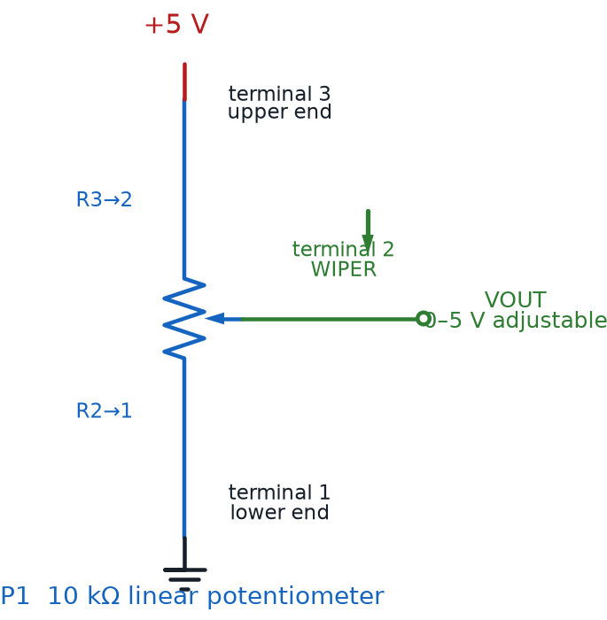
A potentiometer wiper is the sliding or rotating contact inside a potentiometer that touches a resistive strip at one point, dividing the strip's total resistance into two separate parts on either side of that contact point. Turn the knob or slide the lever, and the wiper physically moves along the strip, changing exactly where that division happens. Every voltage-divider behavior you explored back in Chapter 9 traces back to this one moving part.
Diagram: Potentiometer as an Adjustable Voltage Divider
Linear Taper vs. Logarithmic Taper
Not every potentiometer divides its resistance the same way as its knob turns. That difference has a name: taper.
A linear taper is a potentiometer design where resistance changes at a constant, proportional rate as the wiper moves — turn the knob exactly halfway, and you get exactly half the total resistance. Linear taper potentiometers are the easiest to predict and the most common choice for general-purpose circuits, including the light-dimming and voltage-divider circuits this course builds.
A logarithmic taper is a potentiometer design where resistance changes unevenly as the wiper moves, packed tightly at one end of the rotation and stretched out at the other. Human hearing doesn't perceive loudness on a straight-line scale, so a logarithmic taper potentiometer compensates for that curve — which is exactly why almost every volume knob on audio equipment uses one instead of a linear taper.
- Linear taper — resistance rises evenly with rotation; best for general-purpose dimming and voltage dividers
- Logarithmic taper — resistance rises unevenly with rotation; best for volume controls, matching how loudness sounds to human ears
See both curves plotted against the exact same wiper motion in the sim below.
Diagram: Potentiometer Taper Explorer
Potentiometer Taper Explorer
Type: microsim
sim-id: potentiometer-taper-explorer
Library: p5.js
Status: Specified
Purpose: Let students drag a potentiometer's wiper and watch how a linear taper and a logarithmic taper produce different resistance curves for the same wiper motion, then locate the adjustment screw on a rendered trimmer potentiometer.
Bloom Taxonomy: Apply (L3). Bloom Verb: demonstrate, predict.
Learning objective: Given a potentiometer with an adjustable wiper position, predict and observe how a linear taper and a logarithmic taper produce different resistance values for the same wiper rotation, and locate the trim pot adjustment screw on a rendered trimmer potentiometer.
Reuse check: An embeddings search (find-similar-templates, mode=reuse) for "Title: Potentiometer Taper and Trim Pot Explorer | Topic: Potentiometer wiper position, linear taper versus logarithmic taper resistance curve, trim pot adjustment screw | Subjects: Electronics, Beginning Electronics | Grade Level: Junior High | Learning Objectives: Demonstrate how a potentiometer wiper position changes output and compare a linear taper to a logarithmic taper resistance curve" returned a top match of "ADC and Potentiometer Explorer" (dmccreary/learning-micropython, WHAT score 0.4777, recommendation "generate") — below the 0.60 template threshold, and out of scope regardless, since it teaches reading a potentiometer through a microcontroller's ADC, which this no-code course explicitly excludes. A keyword grep of the 3,764-entry catalog for "potentiometer" returned only that same result; grep for "taper" and "trim pot" returned zero hits. This is a new specification.
Canvas layout: Left side shows a rendered potentiometer with a draggable wiper position, plus a rendered trimmer potentiometer variant showing an adjustment screw slot; right side holds a resistance-vs-position graph plotting both taper curves, a taper-type toggle, and an infobox.
Components/elements involved: A rendered rotary potentiometer with a visible wiper indicator; a rendered trim pot with a screw-slot adjustment point; a wiper-position slider (0-100%); a taper toggle (Linear / Logarithmic); a dual-curve resistance graph.
Required interactivity: - Dragging the wiper-position slider moves the wiper on the rendered potentiometer and moves a marker along the currently selected curve on the graph - Toggling Linear/Logarithmic switches which curve is active and updates the resistance readout to match - Hovering the graph at any point shows the wiper percentage and the corresponding resistance value on both curves at once, for direct comparison - Clicking the trim pot's adjustment screw opens an infobox explaining that it is turned with a small screwdriver for an infrequent, precise calibration adjustment, not everyday hands-on control - Button "Reset" returns to a 50% wiper position with Linear taper selected
Default state: Wiper at 50%, Linear taper selected, readout reads "50% rotation = 50% of total resistance," graph showing both curves with the linear curve highlighted.
Data Visibility Requirements: Stage 1: Show the wiper position as a percentage of full rotation Stage 2: Show which taper curve (Linear or Logarithmic) is currently active Stage 3: Show the resulting resistance value read directly off that curve Stage 4: Show both curves overlaid on the same graph for direct visual comparison
Instructional Rationale: An Apply-level "demonstrate/predict" objective calls for a parameter-exploration pattern where dragging the wiper produces an immediate, concrete resistance value on a visible curve, letting students predict the logarithmic curve's unevenness before dragging confirms it.
Color scheme: Blue curve for Linear taper, orange curve for Logarithmic taper, warm orange highlight on the active wiper marker, consistent with the palette used in this chapter's other diagrams.
Responsive behavior: The potentiometer rendering and graph panel stack vertically on narrow screens; the wiper slider remains full-width and touch-draggable.
Implementation: Plain p5.js, not the breadboard-sim-generator — this is a component-behavior explorer rather than a wired circuit, matching the pattern used by this book's other component decoder sims in Chapters 10 and 11.
Same Part, Different Curve Inside
Two potentiometers can look completely identical from the outside — same knob, same three terminals — and still behave totally differently once you turn them, all because of the taper hidden inside. Always check whether a project calls for linear or logarithmic before you grab one from the bin.
Trim Pots and the Adjustment Screw
The potentiometer in this course's kit is built for a very specific kind of use, different from a volume knob you'd turn every day.
A trim pot adjustment screw is the small screw-slot on a trimmer potentiometer, turned with a mini screwdriver to make an infrequent, precise adjustment rather than a knob meant for constant hands-on control. Trim pots are designed to be set once, during calibration, and left alone — exactly the small screwdriver-and-slot part Chapter 9's kit list called out as a "trim pot," and exactly the tool riding on Volt's own tool belt.
Small Turns, Big Changes
A trim pot's adjustment screw often only needs a tiny turn to make a big difference in resistance. Turn it in small increments, checking your circuit's behavior after each one, instead of cranking it a full rotation at once.
Chapter Summary: Key Takeaways
You've now got the deep-dive version of two parts you'd only met at the surface before:
- The diode symbol — triangle into bar — appears on every diode, and a diode's diode band marking shows you which end is the cathode on the real part
- Three specialized types cover different jobs: the rectifier diode converts AC to DC, the Zener diode holds a steady voltage, and the flyback diode protects circuits from a motor's voltage spike
- Diode forward bias lets current through, diode reverse bias blocks it, and every diode's diode current rating sets the safe limit for that forward current
- A red LED, green LED, and blue LED each carry their own forward voltage, so the resistor math from Chapter 10 needs a fresh number for every color
- An LED's LED viewing angle and LED lens shape control where its light goes, and its LED lifespan stretches into tens of thousands of hours, fading gradually instead of burning out
- Inside every potentiometer, a potentiometer wiper divides resistance along a strip, following either a linear taper or a logarithmic taper curve, and a trimmer version adjusts that division with a trim pot adjustment screw
Chapter 13 introduces a part that changes everything your circuits can do: the transistor. You already know how a diode uses one PN junction to control current in a single direction — a transistor uses two, and that second junction is what lets a tiny signal control a much bigger one.
Diode and LED Expert: Unlocked
 Fantastic work, builder — you can now name every diode type in this chapter, predict how any LED color behaves in a circuit, and explain what's really happening inside a potentiometer dial. That's real component-level intuition, the same kind real engineers rely on every day. Current's flowing your way — see you in Chapter 13!