Capacitor Timing and Resistor Values
Summary
This chapter covers the specific resistor values used throughout the course's labs, plus how a capacitor charges and discharges over time and the RC time constant that governs it — a concept that resurfaces later in the 555 timer chapter.
Concepts Covered
This chapter covers the following 19 concepts from the learning graph:
- RC Time Constant
- RC Circuit
- Charging Capacitor
- Discharging Capacitor
- Inductor
- Diode
- LED Polarity
- LED Forward Voltage
- LED Current Rating
- Anode
- Cathode
- 220 Ohm Resistor
- 330 Ohm Resistor
- 1K Resistor
- 10K Resistor
- Resistor Symbol
- Brown Band Value
- Red Band Value
- Resistor Multiplier Band
Prerequisites
This chapter builds on concepts from:
- 1. Electricity Basics: Voltage, Current, and Resistance
- 2. Current, Charge, Units, and Electrical Safety
- 4. Series, Parallel, and Circuit Topology
- 5. Conductors, Batteries, and Circuit Vocabulary Review
- 9. Resistors and Capacitors
Chapter 9 ended with a promise: resistors and capacitors team up in RC timing circuits, and the exact values you choose control how fast things happen. This chapter cashes in that promise — and hands you two brand-new parts along the way.
You'll start with something surprisingly practical: learning to spot the four resistor values that show up over and over in this course's kit, just by glancing at their color stripes. Then you'll meet a component that hasn't appeared in this book yet — the diode — plus its glowing cousin, the LED, and find out exactly why every LED circuit needs a carefully chosen resistor.
By the end of the chapter, you'll watch a capacitor fill up with charge and drain back down, learn how to calculate exactly how long that takes, and get a first look at why that timing math matters. It's the same math hiding inside the 555 timer chip you'll meet a few chapters from now.
New Parts, New Timing Tricks
 Welcome back, builder! Today's lineup is a little unusual — resistor values, a brand-new component called the diode, and capacitors that charge and discharge on a schedule. Different topics, one goal: getting you ready to build real timing circuits. Let's diode into it!
Four Resistors You'll Reach for Again and Again
Before looking at specific values, it helps to recognize the symbol every circuit diagram uses for a resistor, no matter what that resistor's value happens to be. The resistor symbol is the zigzag (or, in some newer diagrams, a plain rectangle) shape that stands in for a resistor in a schematic, wherever it appears and whatever value it carries. You'll see this exact symbol again and again in every wiring diagram from here to the end of the book, so it's worth being able to recognize it on sight.
A kit with hundreds of different resistor values would be overwhelming, and thankfully this course doesn't use one. Nearly every project in this book calls for one of exactly four resistor values, so getting familiar with these four now will save you time later. A 220-ohm resistor is the classic choice for lighting a single standard LED at a bright, safe level. A 330-ohm resistor does a similar job but lets slightly less current through, useful for higher-brightness LEDs or a gentler glow. A 1K resistor — 1,000 ohms — shows up in RC timing circuits and general-purpose jobs where you want to limit current more sharply. A 10K resistor — 10,000 ohms — is the go-to choice for pull-up and pull-down resistors, the wire-steadying job Chapter 9 introduced, and for RC circuits that need to run slowly.
Notice the pattern in how electricians write big resistor values: "K" means "times 1,000," so 1K means 1,000 ohms and 10K means 10,000 ohms. You'll see this shorthand on every resistor package and schematic in this course, and it beats writing four zeros every time.
Meet Them by Feel, Not Just by Sight
 Try sorting a small handful of resistors from your kit into four piles by eye before you read the next section. You'll be surprised how quickly your eyes start recognizing "that's probably a 220" just from the color pattern, even before you double check the bands.
Reading the Bands at a Glance
Every resistor's color stripes encode its value, and Chapter 9 promised you the full decoding system in Chapter 11. This chapter's job is smaller and more useful right now: learning to recognize the bands on exactly the four values above, so you can grab the right part out of a mixed pile without guessing.
Each color used on a resistor stands for a digit. Brown has a brown band value of 1, and red has a red band value of 2 — those are the only two digit-colors this chapter needs, along with orange (3) and black (0), which you'll see in the table below. The first two bands on a resistor spell out a two-digit number using this code. The third band is different: it's the resistor multiplier band, and instead of adding a digit, it tells you how many zeros to tack onto the end — brown means "times 10," red means "times 100," and orange means "times 1,000."
Put it together on a real example: a resistor with red, red, and brown bands reads as digit 2, digit 2, times 10 — giving "22" times 10, or 220 ohms exactly. That's the 220-ohm resistor you'll use for LED after LED in this course.
Here's the process every time you read one of this chapter's four resistors:
- Hold the resistor so any extra band past the third one sits on the right, out of the way — Chapter 9 mentioned that band marks tolerance, and Chapter 11 will finish covering it
- Read the first band's color as the first digit
- Read the second band's color as the second digit
- Read the third band's color as the multiplier, and add that many zeros (or multiply by that power of ten)
- Combine the digits and multiplier to get the resistance in ohms
With that process in hand, the table below reinforces exactly which bands belong to each of this chapter's four resistor values.
| Resistor Value | Band 1 | Band 2 | Band 3 (Multiplier) | Common Use in This Course |
|---|---|---|---|---|
| 220-ohm resistor | Red (2) | Red (2) | Brown (×10) | Lighting a standard LED |
| 330-ohm resistor | Orange (3) | Orange (3) | Brown (×10) | Lighting a higher-brightness LED |
| 1K resistor (1,000 Ω) | Brown (1) | Black (0) | Red (×100) | RC timing, pull-up/pull-down |
| 10K resistor (10,000 Ω) | Brown (1) | Black (0) | Orange (×1000) | Pull-up/pull-down, slower RC timing |
Test your eye against all four patterns in the sim below.
Diagram: Kit Resistor Band Matcher
Kit Resistor Band Matcher
Type: microsim
sim-id: kit-resistor-band-matcher
Library: p5.js
Status: Specified
Purpose: Build fast, reliable recognition of this chapter's four kit resistor values (220 Ω, 330 Ω, 1K, 10K) from their color bands alone, immediately after the reading process and comparison table above.
Bloom Taxonomy: Remember (L1). Bloom Verb: identify, recognize.
Learning objective: Given a rendered resistor showing three color bands drawn from the set {brown, red, orange, black}, identify which of the four kit resistor values (220 Ω, 330 Ω, 1K, 10K) it represents, restricted to only the four band patterns taught in this chapter.
Reuse check: An embeddings search (find-similar-templates, mode=reuse) for "Title: Kit Resistor Color Band Identifier | Topic: Reading resistor color bands for four specific resistor values 220 ohm 330 ohm 1K 10K, brown black orange red bands, multiplier band | Subjects: Electronics, Beginning Electronics | Grade Level: Junior High | Learning Objectives: Identify the four go-to kit resistor values from their color bands" returned a top match of "Resistor Color Code Calculator" (dmccreary/learning-micropython, WHAT score 0.595, recommendation "generate") — below the 0.60 template threshold, so no existing sim is a close enough starting point. This is a new specification. Note for implementation: this repository already has a drawResistor()-style rendering function documented at docs/sims/resistor/resistor.js (physical tan-body resistor with colored bands) that can be reused as the rendering foundation instead of writing band-drawing code from scratch.
Canvas layout: Top area shows one large rendered resistor (tan body, three color bands, lead wires) centered on the canvas; below it, four large buttons labeled "220 Ω," "330 Ω," "1K," and "10K"; a small infobox and a score tracker sit beneath the buttons.
Components/elements involved: A rendered physical resistor with accurate band colors (brown, red, orange, black only, per this chapter's scope); four answer buttons; a "New Resistor" button; a score display ("3/5 correct").
Required interactivity: - On load, and whenever "New Resistor" is clicked, render a resistor showing the bands for a randomly chosen one of the four kit values - Hovering any band on the rendered resistor opens an infobox stating that band's position (first digit, second digit, or multiplier) and its color's meaning - Clicking one of the four value buttons checks the answer: correct answers flash the resistor green and the infobox restates the full digit-and-multiplier breakdown; incorrect answers flash red and the infobox explains what that band pattern actually shows, without naming the correct answer outright - The score tracker increments attempted/correct counts after each guess - Button: "New Resistor" loads a fresh random resistor and clears the flash state
Default state: A 220 Ω resistor (red-red-brown) is shown; infobox reads "Hover a band to learn what it means, or pick an answer below."; score shows "0/0."
Instructional Rationale: A Remember-level "identify/recognize" objective is best served by a flashcard-and-quiz pattern with immediate right/wrong feedback, reinforcing the four specific band patterns just taught rather than testing the full ten-color system, which is out of scope until Chapter 11.
Color scheme: Accurate resistor band colors (brown, red, orange, black) rendered true-to-life; green flash for correct, red flash for incorrect, warm orange highlight on the currently hovered band, consistent with this chapter's other diagrams.
Responsive behavior: The resistor illustration scales to the canvas width; the four answer buttons wrap into a 2×2 grid on narrow screens; hover feedback also triggers on tap for touch devices.
Implementation: p5.js, extending the existing drawResistor() rendering approach from docs/sims/resistor/ in this repository, with quiz logic and scorekeeping layered on top.
Meet the Diode: A One-Way Valve for Current
Every component you've met so far lets current flow through it in either direction — a resistor doesn't care which way current passes, and neither does a switch. The next component you're about to meet breaks that pattern entirely.
A diode is a component that allows electric current to flow through it in only one direction, blocking current that tries to flow the other way. Think of it like a one-way door for electricity: push current through in the allowed direction and it flows freely; try to push it backward and the diode simply refuses, the same way a revolving door won't let you walk in against the flow of traffic.
A diode has two leads, and each one has its own name. The anode is the lead current flows into when the diode is conducting — the "in" side. The cathode is the lead current flows out of — the "out" side. Current that tries to enter through the cathode instead gets turned away at the door, calmly, with no fuss and no spark.
A Door That Only Swings One Way
 Here's the mental model worth keeping: anode in, cathode out, one-way only. Almost every mix-up with diodes and LEDs traces back to forgetting which lead is which — so if you remember nothing else from this section, remember that current has exactly one legal direction through a diode.
In this course, the diode you'll actually hold in your hands is always an LED — a diode built specifically to give off light while it conducts. Plain diodes that don't glow do the exact same one-way job inside countless other devices, from phone chargers to solar panels, but they aren't part of this course's kit. Everything you learn about anode, cathode, and one-way current flow here applies to both.
LEDs: Diodes Built to Glow
You've wired LEDs since Chapter 1, always following instructions about which way to point them. Now you know why: an LED is a diode, and diodes only conduct one way.
Because an LED is a diode, its two leads follow the exact same anode-and-cathode naming, and getting that orientation right is called LED polarity — the requirement that an LED's anode and cathode connect to the correct sides of a circuit for current, and therefore light, to flow at all. Most LEDs mark their cathode with a flat spot on the plastic case and a shorter lead wire, exactly like the electrolytic capacitor's stripe from Chapter 9 marks its negative side. Flip an LED backward and current simply can't get through — the diode blocks it, just as it's supposed to.
Backwards LEDs Just Stay Dark
 Good news for nervous builders: at the safe, low voltages this course uses, a backwards LED won't get damaged — it will simply refuse to light. If your LED stays dark the moment you power up a new circuit, flipping it around is the very first thing to try.
An LED doesn't conduct current the instant any voltage at all is applied — it needs a minimum push to start conducting and glowing, called its LED forward voltage: the voltage drop across a conducting LED, roughly constant regardless of how much current is flowing through it. A standard red LED has a forward voltage around 2 volts; other colors differ slightly, with blue and white LEDs typically needing closer to 3 volts.
Voltage alone doesn't tell the whole story, though. Every LED also has an LED current rating — the maximum current an LED can safely handle before it overheats and burns out, typically somewhere around 20 milliamps (0.020 amps) for a standard 5mm LED. This is exactly the number Chapter 1's Ohm's Law calculation protected against, and it's exactly why every LED circuit needs a current limiting resistor in series, the job Chapter 9 named. Skip the resistor, and there's nothing standing between the LED and a current far past its rating.
Put LED forward voltage, LED current rating, and Ohm's Law together and you get a simple, reusable formula for picking that resistor.
The LED Current-Limiting Resistor Equation
where:
- \( R \) is the current-limiting resistor value, in ohms
- \( V_{supply} \) is the supply voltage powering the circuit
- \( V_f \) is the LED's forward voltage
- \( I \) is the desired LED current, in amps, kept at or below the LED's current rating
Try the numbers on a real example: a 5-volt supply, a red LED with a 2-volt forward voltage, and a target current of 0.015 amps (15 milliamps, safely under the usual 20 mA rating). That gives \( R = \frac{5 - 2}{0.015} = 200 \) ohms — close enough that you'd reach for your kit's 220-ohm resistor, the exact value from earlier in this chapter, bands and all.
Before moving on, the table below reinforces the diode and LED terminology just introduced.
| Term | What It Means |
|---|---|
| Diode | A component that lets current flow in one direction only |
| Anode | The lead current flows into |
| Cathode | The lead current flows out of — often marked by a flat edge or shorter lead |
| LED Polarity | The requirement that anode and cathode connect the correct way for the LED to light |
| LED Forward Voltage | The voltage drop across a lit LED, roughly 2 V for red, closer to 3 V for blue/white |
| LED Current Rating | The maximum safe current, typically around 20 mA for a standard LED |
See every one of these ideas working together on a real breadboard circuit below.
Diagram: LED with Current-Limiting Resistor Breadboard Circuit
LED with Current-Limiting Resistor Breadboard Circuit
Type: microsim
sim-id: led-current-limiting-resistor-circuit
Library: p5.js
Status: Specified
Purpose: Let students identify an LED's anode and cathode on a rendered breadboard circuit, flip its orientation to see why LED polarity matters, and swap resistor values to see how the current-limiting resistor equation connects a chosen value to real LED brightness and safety.
Bloom Taxonomy: Understand (L2) / Apply (L3). Bloom Verb: identify, demonstrate, calculate.
Learning objective: Given a rendered breadboard LED circuit with a swappable current-limiting resistor, identify the LED's anode and cathode, predict what happens when the LED is wired backwards, and calculate the resulting current for different resistor choices using the current-limiting resistor equation.
Reuse check: An embeddings search (find-similar-templates, mode=reuse) for "Title: LED with Current Limiting Resistor Breadboard Circuit | Topic: LED polarity, anode, cathode, current limiting resistor, breadboard wiring | Subjects: Electronics, Beginning Electronics | Grade Level: Junior High | Learning Objectives: Identify LED anode and cathode and demonstrate why a current-limiting resistor is required to protect an LED on a breadboard circuit" returned a top match of "Breadboard" (dmccreary/microsims, WHAT score 0.6415, recommendation "template") — above the 0.60 template threshold but below the 0.75 reuse threshold, so this sim's rendered breadboard, tie-point layout, and component-placement approach should be used as a starting point rather than reused as-is, since it does not already include an LED, resistor, or polarity logic. Template: https://github.com/dmccreary/microsims/tree/main/docs/sims/breadboard
This is also a strong candidate for the breadboard-sim-generator skill, since it needs a rendered breadboard with real tie-point positions and animated current flow tied to component orientation.
Canvas layout: Left/main area shows a rendered half-size breadboard with a battery pack, an LED (long/short lead and flat-edge cathode visible), and a resistor wired in series; right side panel holds a "Flip LED" button, a resistor-value selector (220 Ω, 330 Ω, 1K, 10K, and a "no resistor" option), a calculated current readout, and an infobox.
Components/elements involved: A rendered breadboard with power and ground rails; a battery pack; an LED with clearly rendered anode (longer lead) and cathode (shorter lead, flat edge); a swappable resistor; connecting wires; an animated current-flow indicator along the wires.
Required interactivity: - Click "Flip LED" to reverse the LED's orientation on the breadboard; when reversed, the LED stays dark, current-flow animation stops at the LED, and the infobox explains that the diode is blocking current in this direction with no damage at this course's low voltage - Select a resistor value from the dropdown (220 Ω, 330 Ω, 1K, 10K, or "no resistor"); the calculated current readout updates live using the current-limiting resistor equation, the LED's brightness animation scales with current, and choosing "no resistor" flags a clear on-screen warning that current would exceed the LED's safe rating - Hover the LED to open an infobox labeling the anode and cathode and stating that LED's forward voltage - Hover the resistor to see the equation with the current supply voltage, forward voltage, and resistor value substituted in - Button: "Reset" returns to the default correctly-wired, 220 Ω state
Default state: LED correctly oriented (anode toward supply), 220 Ω resistor selected, \( V_{supply} \) fixed at 5 V, LED lit at normal brightness, infobox reads "Current flows from anode to cathode — this LED is wired correctly, drawing about 14 mA."
Instructional Rationale: An Understand/Apply objective combining "identify" and "calculate" benefits from a manipulable breadboard simulation rather than a static diagram, since students must both recognize the physical polarity cues (flat edge, lead length) and see the numeric consequence of each resistor choice tied directly to the equation just taught.
Color scheme: Warm orange for the currently highlighted component, green glow on the LED when correctly lit, red warning flash for the "no resistor" or reversed-LED states, consistent with the palette used in this chapter's other diagrams.
Responsive behavior: Breadboard view and the control/infobox panel stack vertically on narrow screens; the resistor dropdown and Flip LED button remain full-width and touch-friendly.
Implementation: p5.js, built on the breadboard-sim-generator rendering approach (real tie-point hole grid, component placement, and animated current flow), extending the template referenced above with an LED, a swappable resistor, and live current calculation.
RC Circuits: Capacitors and Resistors Working Together
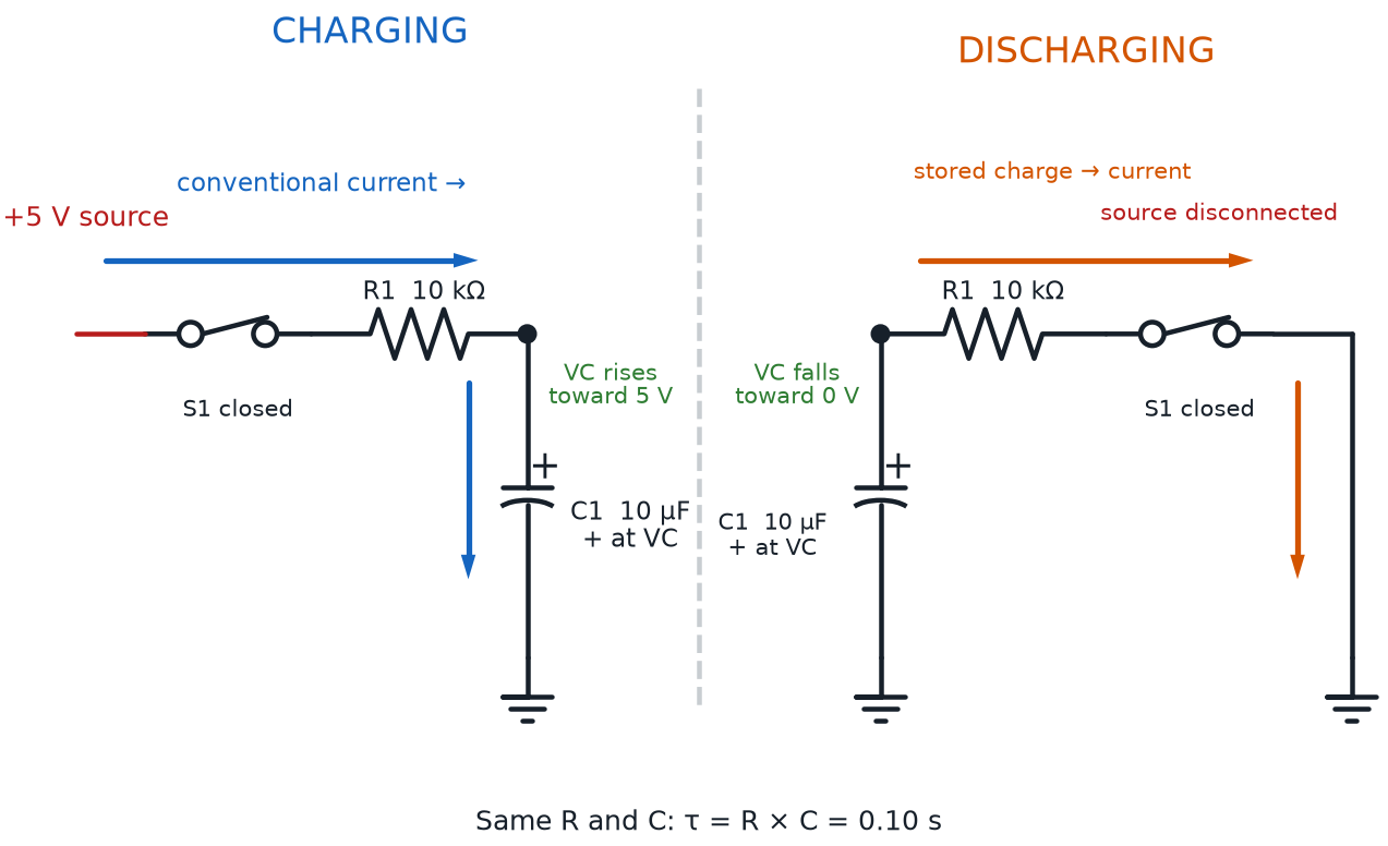
Chapter 9 introduced the capacitor on its own — a part that stores electric charge and releases it later. On its own, though, a capacitor connected straight to a battery would charge almost instantly, far too fast to be useful for timing anything. Add a resistor, and everything changes.
An RC circuit is a circuit built from a resistor and a capacitor connected together, where the resistor controls how quickly the capacitor can charge or discharge. The "RC" in the name is short for exactly those two parts, resistor and capacitor, working as a pair rather than alone. Without the resistor, current would rush into the capacitor all at once; with it, current is forced to trickle in gradually, spreading the charging process out over a measurable stretch of time.
Picture filling a bucket through a garden hose instead of dumping a full pitcher into it all at once — the bucket (the capacitor) still ends up full, but the hose (the resistor) controls exactly how fast that happens. That slow-fill process has a name: a charging capacitor is a capacitor whose voltage is rising over time as current flows into it through a resistor, starting near zero and climbing toward the supply voltage. Run the process in reverse and you get a discharging capacitor — a capacitor whose voltage is falling over time as it releases its stored charge back out through a resistor, starting at its charged voltage and dropping back toward zero.
Same Water-Pipe Idea, New Job
Remember the water-pipe picture from Chapter 1, where a bigger resistor meant a narrower pipe and less flow? The exact same idea is at work here — a bigger resistor slows the "fill rate" and "drain rate" of a capacitor, turning an instant process into one you can actually time.
Both charging and discharging follow the same basic shape every single time: fast movement at the start, then a gradual slowdown as the capacitor gets closer to its final voltage — never truly instant, and never truly abrupt.
Diagram: RC Charging and Discharging Circuit
The RC Time Constant: Putting a Number on "How Fast"
Saying a capacitor charges "gradually" is a start, but engineers need an actual number to design real circuits — a blinking LED, an alarm delay, a timed buzzer. That number has a name.
The RC time constant is the amount of time it takes an RC circuit's capacitor to charge or discharge by a fixed, predictable fraction of the way toward its new voltage, calculated directly from the resistor and capacitor values. It's written using the Greek letter tau, and the formula behind it is refreshingly simple.
The RC Time Constant Equation
where:
- \( \tau \) (tau) is the RC time constant, measured in seconds
- \( R \) is the resistance of the circuit's resistor, in ohms
- \( C \) is the capacitance of the circuit's capacitor, in farads
A bigger resistor or a bigger capacitor both stretch out \( \tau \), making the circuit charge and discharge more slowly; shrink either one, and the circuit speeds up. One time constant isn't "fully charged," though — it's just the first, well-defined checkpoint along the way. Engineers use a handy rule of thumb to describe the rest of the curve, reinforced in the table below.
| Time Elapsed | Percent Charged |
|---|---|
| 1 × \( \tau \) | About 63% |
| 2 × \( \tau \) | About 86% |
| 3 × \( \tau \) | About 95% |
| 5 × \( \tau \) | About 99% (treated as "fully charged") |
Explore the curve for yourself, with real kit resistor and capacitor values, in the sim below.
Diagram: RC Charge and Discharge Curve Explorer
RC Charge and Discharge Curve Explorer
Type: microsim
sim-id: rc-charge-discharge-explorer
Library: p5.js
Status: Specified
Purpose: Let students adjust resistor and capacitor values in a simple RC circuit and watch the voltage-vs-time charge and discharge curve update live, connecting the RC time constant equation and the percent-charged rule-of-thumb table above to a concrete, visible graph.
Bloom Taxonomy: Apply (L3). Bloom Verb: calculate, demonstrate.
Learning objective: Given an RC circuit with adjustable resistor and capacitor values, calculate the resulting RC time constant and predict, then verify, how long the capacitor takes to reach roughly 63%, 86%, 95%, and 99% of its final voltage while charging or discharging.
Reuse check: An embeddings search (find-similar-templates, mode=reuse) for "Title: RC Charge and Discharge Curve | Topic: RC time constant, capacitor charging and discharging through a resistor over time | Subjects: Electronics, Beginning Electronics | Grade Level: Junior High | Learning Objectives: Predict and observe how a capacitor's voltage rises during charging and falls during discharging through a resistor, and how changing R or C changes the RC time constant" returned a top match of "Capacitor Charging and Discharging" (dmccreary/intro-to-physics-course, WHAT score 0.6571, recommendation "template") — above the 0.60 template threshold but below the 0.75 reuse threshold, so this sim's exponential charge/discharge graphing approach is a strong starting point but needs its controls simplified to this chapter's junior-high, non-calculus framing (rule-of-thumb percentages instead of the exponential formula). Template: https://github.com/dmccreary/intro-to-physics-course/tree/main/docs/sims/capacitor-charging-discharging
Canvas layout: Left/main area shows a voltage-vs-time line graph with vertical dashed markers at 1τ, 2τ, 3τ, and 5τ; right side panel holds an R slider, a C slider, a live τ readout with the equation substituted in, a Charge/Discharge toggle, and an infobox.
Components/elements involved: A labeled voltage-vs-time graph (Y-axis: Voltage, X-axis: Time); a small capacitor icon showing current charge level as a fill bar; a Charge/Discharge toggle switch; two sliders for \( R \) and \( C \).
Required interactivity: - Drag the \( R \) slider with snap points at this chapter's kit values (220 Ω, 330 Ω, 1K, 10K); the graph curve and τ readout update immediately - Drag the \( C \) slider (1 µF to 1,000 µF); the graph curve and τ readout update immediately - Toggle between "Charge" and "Discharge" to animate the curve rising toward the supply voltage or falling back toward zero - Hover any point on the curve to open an infobox showing elapsed time in multiples of τ and the approximate percent charged, matching the rule-of-thumb table above - Button: "Reset" returns to the default state
Default state: \( R \) = 1,000 ohms (1K resistor), \( C \) = 100 µF, \( \tau \) readout shows "τ = 1,000 Ω × 0.0001 F = 0.1 seconds," curve in Charge mode.
Data Visibility Requirements: Stage 1: Show the current \( R \) and \( C \) slider values Stage 2: Show the equation \( \tau = R \times C \) with those exact numbers substituted in Stage 3: Show the resulting \( \tau \) value and the animated curve, with the 1τ/2τ/3τ/5τ markers and their percent-charged values labeled on the graph
Instructional Rationale: An Apply-level "calculate/demonstrate" objective calls for a parameter-exploration pattern with the equation's real numbers visible at every stage, so students can connect each slider movement directly to a changing τ value and a changing curve shape, rather than watching an unlabeled animation.
Color scheme: Warm orange for the currently dragged slider, blue curve while charging, gray curve while discharging, consistent with the palette used in this chapter's other diagrams.
Responsive behavior: Graph area and the slider/readout panel stack vertically on narrow screens; sliders remain full-width and touch-draggable.
Implementation: p5.js, adapting the graphing approach from the template referenced above, simplified to rule-of-thumb percentage markers instead of the full exponential charging formula to match this course's non-calculus, junior-high framing.
The Math Feels Abstract — That's Normal
 If multiplying a resistor by a capacitor to get "seconds" feels strange the first time, you're right on schedule — nearly every builder needs a few tries with the sim above before it clicks. Keep this idea in your back pocket: a whole chapter later, the 555 timer chip you'll build with uses this exact same RC math to decide how fast it blinks and beeps.
One More Reactive Part: The Inductor
Capacitors aren't the only component that stores energy and resists sudden change — there's one more worth knowing by name, even though your kit doesn't include it.
An inductor is a component that stores energy in a magnetic field when current flows through it, resisting sudden changes in current the way a capacitor resists sudden changes in voltage. Where a capacitor pushes back against a voltage that's changing too fast, an inductor pushes back against a current that's changing too fast — the two components are natural opposites, both classified as "reactive" parts because both react to change rather than simply resisting current at a fixed rate.
This course's $50 kit doesn't include a standalone inductor, and you won't need one to complete any project in this book. Inductors show up constantly in power supplies, motors, and radio circuits — more advanced territory than this course covers — so for now, just knowing the name, the basic idea, and how it contrasts with a capacitor is exactly enough.
Chapter Summary: Key Takeaways
You've covered an unusually wide mix of ideas in this chapter, and every one of them will show up again later in the course.
- The resistor symbol appears in every schematic, and this chapter's four go-to values — the 220 Ohm Resistor, 330 Ohm Resistor, 1K Resistor, and 10K Resistor — cover nearly every project ahead
- Reading a brown band value of 1, a red band value of 2, and a resistor multiplier band lets you recognize all four of those values by their color bands alone
- A diode lets current flow in only one direction, from its anode to its cathode
- An LED is a diode built to glow, so getting its LED polarity right matters, its LED forward voltage sets the minimum voltage needed to light it, and its LED current rating sets the resistor math that protects it
- An RC circuit pairs a resistor and capacitor so that a charging capacitor or discharging capacitor changes voltage gradually instead of instantly, at a rate set by the RC time constant
- An inductor is the magnetic-field cousin of the capacitor — good to know by name, even without one in your kit
Chapter 11 picks up right where this one left off: the full ten-color resistor code, every multiplier and tolerance band, and the rest of the capacitor details Chapter 9 promised. You've already got a head start — four values and four colors down, six more colors to go.
Timing Circuits: Unlocked
 Huge chapter, builder — you can spot your kit's go-to resistors on sight, wire an LED the right way around without a second thought, and explain why an RC circuit takes time instead of happening all at once. That's real timing-circuit intuition, and it's exactly what the 555 timer chapter is counting on you to bring. Current's flowing your way — see you in Chapter 11!