Using a Multimeter
Summary
This chapter teaches students to read voltage, current, resistance, and continuity with a multimeter, and to test individual components (resistors, diodes, LEDs) before or after placing them in a circuit.
Concepts Covered
This chapter covers the following 19 concepts from the learning graph:
- Multimeter
- Digital Multimeter
- Analog Multimeter
- Multimeter Display
- Multimeter Dial Settings
- Auto-Ranging Multimeter
- Multimeter Probes
- Multimeter Safety
- Voltage Measurement
- Measuring In-Circuit Voltage
- Measuring Battery Voltage
- Current Measurement
- Reading Milliamps
- Resistance Measurement
- Verifying Resistor Color Code
- Continuity Testing
- Continuity Beep Tone
- Testing A Switch
- Voltage Range Selection
Prerequisites
This chapter builds on concepts from:
- 1. Electricity Basics: Voltage, Current, and Resistance
- 2. Current, Charge, Units, and Electrical Safety
- 6. Meet Your Breadboard
- 9. Resistors and Capacitors
Every circuit you've built so far has asked you to trust a promise. Chapter 12 promised a red LED drops about 1.9 volts. Chapter 18 promised a spinning motor's own back-EMF spikes dangerously at switch-off. You've had to take those promises on faith, checking your work only by whether an LED glowed or a motor turned.
That changes today. A multimeter is a handheld tool that measures voltage, current, resistance, and continuity in a circuit, turning every promise this book has made into a number you can check yourself. Once you know how to use one, you never have to guess whether a circuit is broken, or trust that a resistor really is 220 ohms — you can measure it and know for certain.
Your New Superpower: Proof
 Welcome back, builder! Every circuit you've wired so far, you've had to trust was working the way the book promised. Starting today, you don't have to trust anything — you can measure it yourself, on any circuit, any time you want proof. Let's light it up!
Meet Your New Superpower Tool: The Multimeter
A multimeter earns its name honestly. It's really several separate meters built into one compact tool. A voltmeter, an ammeter, and an ohmmeter would normally be three different devices, but a multimeter combines all three, plus a continuity tester, behind a single dial and one pair of probes.
Multimeters come in two basic styles, and knowing the difference helps you recognize either one on sight. A digital multimeter is a multimeter that shows its reading as numbers on an electronic screen, the kind almost every modern kit — including this course's — includes today. An analog multimeter is an older style of multimeter that shows its reading with a moving needle sweeping across a printed scale, instead of digital numbers. Analog multimeters still turn up in older toolboxes, but a digital multimeter is easier to read precisely, since you never have to guess exactly where a needle sits between two printed lines.
Three Meters in One
 Picture three separate boxes: one that only measures voltage, one that only measures current, one that only measures resistance. A multimeter is what happens when an engineer decides carrying three boxes around is silly, and builds one dial that switches between all three jobs — plus a bonus continuity tester thrown in for free.
Over the rest of this chapter, you'll learn every one of a multimeter's core jobs, one at a time:
- Measuring voltage, across a battery or across a single component
- Measuring current, in milliamps, flowing through a circuit
- Measuring resistance, to check a resistor's real value against its color code
- Testing continuity, to instantly confirm two points are truly connected
Before any of those jobs make sense, you need to know how the meter itself talks to you, and how you touch it to a circuit.
Reading the Meter: Display and Probes
The multimeter display is the screen, usually a small LCD, that shows the numeric result of whatever the meter is currently measuring. On a digital multimeter, the display updates continuously while the meter is powered on, alongside a unit label — V for volts, mA for milliamps, or Ω for ohms — telling you what kind of measurement you're looking at. A display showing only "1" or the letters "OL" (short for overload) usually means the value is too large for the current range, not that the meter is broken.
The multimeter probes are the two wire leads, tipped with metal points, that carry a measurement from the circuit into the meter. Every multimeter's probes follow the same color convention: red for the positive probe, black for the negative, or "common," probe. The red probe plugs into a jack usually labeled "VΩmA," used for voltage, resistance, and, on most small meters, current. The black probe plugs into a jack labeled "COM," short for common, and it stays there for every single measurement you'll make in this chapter.
Before you touch a probe to a real circuit, take a labeled tour of a digital multimeter's parts in the diagram below.
Diagram: Multimeter Anatomy Explorer
Multimeter Anatomy Explorer
Type: infographic
sim-id: multimeter-anatomy-explorer
Library: p5.js
Status: Specified
Purpose: Let students click or hover every labeled part of a digital multimeter's body — display, dial, probes, and jacks — to build a mental map of the tool before they use it on a real or simulated circuit.
Bloom Taxonomy: Remember (L1) / Understand (L2). Bloom Verb: identify, describe.
Learning objective: Given a labeled illustration of a digital multimeter, identify the display, the rotary dial and its measurement positions, the red and black probes, and the COM and VΩmA jacks, and describe what each part does.
Reuse check: An embeddings search (find-similar-templates, mode=reuse) for "Title: Multimeter Anatomy Explorer | Topic: digital multimeter display, dial settings, probes, COM jack, VOhmmA jack, auto-ranging | Subjects: Electronics, Electric Circuits | Grade Level: Junior High | Learning Objectives: Identify the parts of a digital multimeter (display, dial, probes, jacks) by clicking labeled hotspots" returned a top match of "Vertical Line Test Explorer" (dmccreary/pre-calc, WHAT score 0.6015, recommendation "template") — above the 0.60 template threshold on the numeric score alone, but a manual sanity check rejects it: the candidate is a High School Geometry sim about the vertical line test, with no topical, component, or interaction overlap with a multimeter's parts. Treated as generate rather than template, per the reuse-check rule that a clearly wrong subject/grade-level match overrides a borderline score. A keyword grep of the 3,764-entry MicroSim catalog for "multimeter," "voltmeter," "ammeter," "ohmmeter," and "probe" returned no relevant matches. New specification.
Canvas layout: A large, centered illustration of a handheld digital multimeter (rounded rectangular body, yellow or orange casing) fills most of the canvas, with a small infobox panel below or beside it.
Components/elements involved: The multimeter's LCD display (top of the body, showing a sample reading like "4.98" with a "V" unit label); the rotary dial (center of the body, with position marks for OFF, V (DC volts), mA, Ω, and a continuity speaker-wave icon); the black probe plugged into a jack labeled "COM"; the red probe plugged into a jack labeled "VΩmA"; the two probe tips, shown as separate wire leads trailing off the bottom of the illustration.
Required interactivity: - Clicking or hovering the display opens an infobox explaining that it shows the numeric result and unit of the current measurement, and that "OL" means the value is too large for the range - Clicking or hovering the dial opens an infobox explaining that its position selects which of the meter's jobs (voltage, current, resistance, continuity) is active, and that it must always match the measurement being attempted - Clicking or hovering the COM jack opens an infobox explaining that the black probe always plugs in here, for every measurement mode - Clicking or hovering the VΩmA jack opens an infobox explaining that the red probe plugs in here for voltage, resistance, and small-current measurements - Clicking or hovering either probe tip opens an infobox reinforcing the red-positive, black-negative color convention - Button "Reset" clears any selected hotspot and returns to the default state
Default state: No hotspot selected; infobox reads "Click any part of the multimeter to learn what it does."
Instructional Rationale: A Remember/Understand-level "identify/describe" objective is best served by a clickable labeled illustration with static, discoverable hotspots — not animation — so students can explore each part at their own pace and revisit any one of them before moving on to actual measurements.
Color scheme: Yellow-orange meter body (matching common real-world multimeter casings), blue highlight ring around the currently selected hotspot, red and black leads drawn in their true probe colors.
Responsive behavior: The multimeter illustration scales to canvas width; the infobox panel moves below the illustration on narrow screens instead of beside it.
Implementation: Plain p5.js, not the breadboard-sim-generator — this is a standalone labeled-component illustration, not a wired circuit. Static hotspot regions with hover/click detection and a single infobox panel.
Red Goes to Positive, Every Time
 Here's a habit worth building on day one: red probe to the positive side, black probe to the negative or common side, every single time. Lock in that muscle memory now, and you'll never fumble for which lead goes where on a bigger, more intimidating meter later.
Setting the Dial: Modes, Ranges, and Auto-Ranging
The multimeter dial settings are the positions on the meter's central rotary switch, each one telling the meter which job to perform next — voltage, current, resistance, or continuity. Turning the dial doesn't just relabel the display; it reconfigures the meter's internal circuitry to behave like a completely different instrument, which is exactly why picking the right dial setting before you touch a probe to anything matters so much.
Older and simpler multimeters add one more decision on top of the mode itself. Voltage range selection is the process of manually choosing a numeric range — such as 2V, 20V, or 200V — that comfortably fits the value you expect to measure, so the meter displays your reading with the most useful precision. Pick a range too small, and the meter shows "OL" because your value is bigger than the range allows. Pick a range too large, and you still get a reading, but with fewer useful digits, similar to trying to read a bathroom scale that only shows whole tons.
Most beginner-friendly digital multimeters remove that extra step entirely. An auto-ranging multimeter is a multimeter that automatically detects the correct range for whatever you're measuring, instead of requiring you to select one by hand. Auto-ranging multimeters are common in inexpensive kits today, and they're the friendliest choice for a first meter — you just pick the mode (V, mA, Ω, or continuity), and the meter handles the rest.
Before you set a dial to anything, it helps to see every mode side by side, along with what its symbol looks like and when you'll actually reach for it.
| Dial Setting | Symbol | What It Measures | When You'll Use It in This Course |
|---|---|---|---|
| OFF | — | Nothing — powers the meter down | Whenever the meter is not actively in use, to save its battery |
| DC Voltage | V with a straight line (V⎓ or DCV) | Voltage difference between two points | Checking a battery's voltage, or a component's voltage drop |
| DC Milliamps | mA | Current flowing through the circuit | Reading how much current an LED or motor branch draws |
| Resistance | Ω | A component's resistance, in ohms | Verifying a resistor's value against its color code |
| Continuity | A speaker or sound-wave icon | Whether two points are electrically connected | Testing a switch, a wire, or a suspect connection |
This course's circuits are entirely low-voltage DC, so you'll only ever need the five rows above. A real multimeter usually has an AC voltage position too, marked with a wavy line instead of a straight one — you can safely ignore it here, since every project in this book runs on safe, battery- or USB-powered DC.
Multimeter Safety: Read This Before You Touch a Probe
Multimeter safety is the set of habits that keep both you and your meter safe while measuring a circuit, and almost every multimeter mistake traces back to one of two causes: the wrong dial setting, or the wrong probe jack.
Dial and Jacks First, Probes Second
 Two mistakes cause nearly every multimeter close call. First, touching probes set to resistance or continuity mode onto a powered circuit sends that circuit's own voltage backward into the meter's tiny internal test circuit instead of a clean reading — always check your dial before touching a live circuit. Second, leaving the dial on current mode and then touching the probes straight across a voltage source, the way you would for a voltage reading, is basically a dead short through the meter, and it can pop the meter's internal fuse instantly. Always set the dial and confirm the jacks before the probes ever touch the circuit.
A few extra rules round out safe multimeter habits, and they're worth committing to memory before your first real measurement:
- Always start with the dial on the mode you actually intend to measure, never guess and check
- Always confirm the red probe is in the jack meant for that mode before touching anything
- Never leave stray probe tips touching each other or two different points by accident while the meter is on
- Turn the dial back to OFF when you're done, so the meter's own battery isn't drained overnight
This course's voltages, five volts from a USB supply or a small battery pack, are safe to touch with bare hands. Building careful dial-and-jack habits now is what keeps you safe later, on bigger projects with bigger voltages.
Measuring Voltage: The Easiest Place to Start
Voltage measurement is the job of comparing the electrical potential between two points and reporting the difference, and it's the gentlest mode to start with because it never requires you to break a circuit open. You simply touch the red probe to one point, the black probe to another, and read the difference straight off the display — the circuit keeps running exactly as it was the whole time.
Diagram: Voltage, Current, and Resistance Measurement Connections
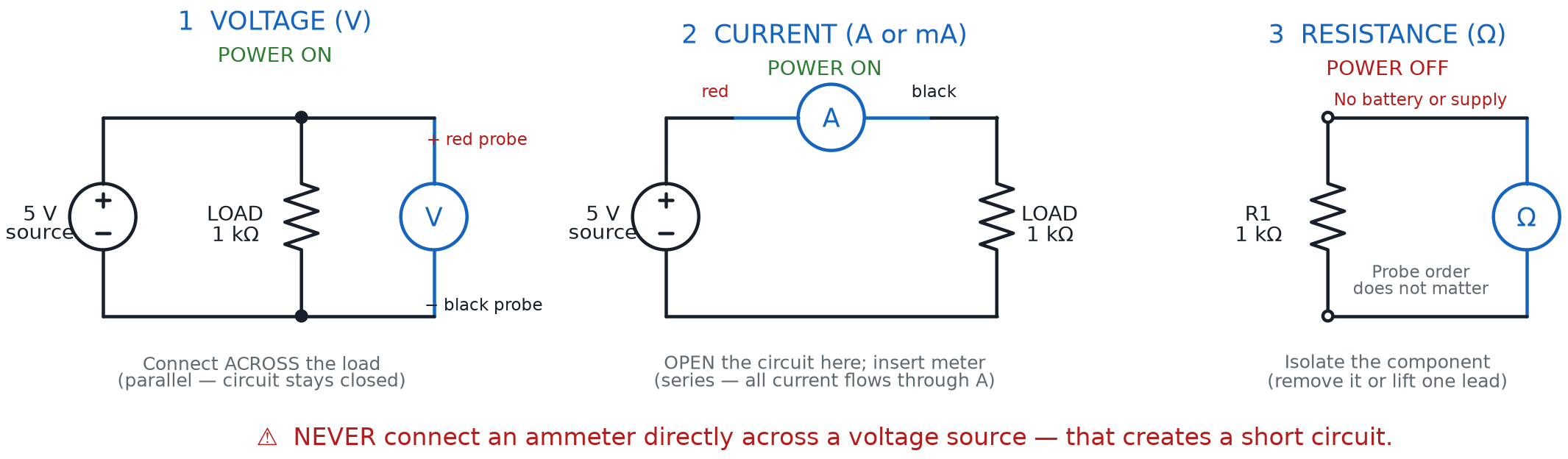
Measuring battery voltage is the simplest voltage check you'll ever make. Set the dial to DC voltage, touch the red probe to the battery's positive terminal and the black probe to its negative terminal, and read the result. A fresh AA battery reads close to 1.5 V; a rundown one might read closer to 1.1 V, even though it still looks identical on the outside. This is exactly how you'll catch a "dead" battery before it ruins an afternoon of building.
Measuring in-circuit voltage means taking that same red-probe/black-probe technique and applying it to a circuit that's already wired and powered on, instead of a bare battery. Touch the probes across a resistor's two leads, or across an LED's two legs, and the meter reports the voltage drop across that exact part — the same voltage drop this book has been describing in words since Chapter 9. Measuring across a lit red LED should read close to the 1.9 V forward voltage Chapter 12 promised, turning a chapter's worth of promises into a number on a screen.
Measuring Current: Breaking the Circuit on Purpose
Voltage measurement never disturbs a circuit, but current measurement works differently by necessity. Current measurement is the job of finding how much charge is flowing per second through a specific point, and a multimeter can only measure it by becoming part of the current's path itself. That means you must open the circuit at one spot and insert the meter's probes into that gap, letting every electron pass through the meter on its way around the loop — a meter set to voltage mode never needs this extra step, which is exactly why current measurement takes more setup.
Most of the currents you'll measure in this course are small. Reading milliamps means expecting values in the tens, not the thousands, of a single amp — a lit LED typically draws somewhere between 10 and 20 mA, and even a small DC motor rarely exceeds a few hundred milliamps. That's exactly why the dial's current position is usually labeled "mA" rather than "A," and why the red probe often stays in the same VΩmA jack used for voltage and resistance on a small meter.
Converting Amps to Milliamps
where:
- \( I_{mA} \) is the current, measured in milliamps
- \( I_{A} \) is that same current, measured in amps
A red LED drawing 0.015 A is the same current as 15 mA — just written with a more convenient unit for the small currents this course's circuits actually use. Reading a meter that says "15.2" while its dial and jack are both set for mA tells you the exact same thing as reading "0.0152" on an A-scale meter, just with fewer zeros to count.
Measuring Resistance: Checking a Part Before (or After) It's Built In
Resistance measurement is the job of finding how strongly a component opposes current flow, reported in ohms. Unlike voltage or current, a multimeter measures resistance by sending its own small test current through the component and calculating the resistance from the result — which only works correctly if no other power source is also pushing current through that same part at the same time.
Unplug It Before You Ohm It
Resistance mode is the one mode that truly cannot handle a powered circuit. Always disconnect the battery, or better yet, lift the component out of the circuit entirely, before switching the dial to Ω. Measuring resistance on a still-powered circuit gives a meaningless reading at best, and risks the meter at worst.
Verifying a resistor's color code is one of the most satisfying things you can do with resistance mode. Chapter 11 handed you the complete ten-color code table, letting you read a resistor's value from its bands alone. Now you don't have to trust your eyes and memory alone — pull a resistor from your kit, decode its bands the way Chapter 11 taught, then touch a meter's probes across its two leads and see how close the two numbers land. A resistor coded for 220 ohms typically measures somewhere between 209 and 231 ohms, comfortably inside its printed tolerance band.
Two Ways to Read the Same Number
Decoding a color band and measuring with a meter are two completely different skills landing on the same answer — one uses your eyes and memory, the other uses electricity itself. When they agree, that's not luck. That's you, twice-checking your own work like a real engineer. (And if a resistor's coded value and its measured value are wildly different, trust the meter — you may have grabbed the wrong resistor by mistake.)
Continuity Testing: The Fastest Check in Your Toolkit
Continuity testing is a special, faster version of resistance measurement that answers one simple yes-or-no question: are these two points electrically connected? Instead of making you read a precise ohms value, continuity mode watches for a resistance close to zero and reacts instantly.
The continuity beep tone is the audible signal a multimeter makes the instant it detects a connection in continuity mode, letting you check a wire or connection without even looking at the display. That beep is what makes continuity testing the fastest check in your entire toolkit — perfect for confirming a jumper wire is good, a fuse hasn't blown, or two holes on your breadboard are truly part of the same row.
Testing a switch is a perfect first use for continuity mode, and it ties directly back to Chapter 6's lesson on how a breadboard's rows connect. With the switch disconnected from any power source, touch the two probes to its terminals. An open switch stays silent; a closed switch beeps immediately. This confirms a switch actually works before you ever wire it into a bigger circuit, saving you from chasing a "broken circuit" that was really just a broken switch all along.
There's No Wrong Way to Get a Beep
 If voltage math and milliamp conversions felt like a lot in this chapter, continuity testing is your reward for sticking with it. There's no formula, no range to pick, nothing to calculate — just touch, listen, and know. Every builder's favorite multimeter mode is usually this one.
Put It All Together: Try the Virtual Multimeter
Before you pick up a real meter, it helps to practice on a circuit where nothing can go wrong. The table below reinforces what you've already learned, gathering every measurement mode's setup into one place you can check before trying the sim.
| Measurement | Probe Placement | Circuit Power | What a Good Reading Looks Like |
|---|---|---|---|
| Voltage | Across (parallel to) the two points of interest | Powered ON | A stable number near the expected value |
| Current | In series, inserted into a break in the circuit | Powered ON | A milliamp value matching an Ohm's Law estimate |
| Resistance | Across the component's two leads | Powered OFF, ideally out of the circuit | An ohms value close to the coded or expected value |
| Continuity | Across the two points being checked | Powered OFF | A beep tone, for a resistance near zero |
Now put every mode to work on one virtual breadboard, complete with a real dial and real probes.
Diagram: Virtual Multimeter Breadboard
Virtual Multimeter Breadboard
Type: microsim
sim-id: virtual-multimeter-breadboard
Library: p5.js
Status: Specified
Purpose: Let students select a multimeter dial mode and touch virtual probes to labeled test points on a wired breadboard circuit, reading a live voltage, current, resistance, or continuity result for each one — practicing every mode this chapter taught before ever picking up a real meter.
Bloom Taxonomy: Apply (L3). Bloom Verb: demonstrate, measure, verify.
Learning objective: Given a multimeter dial mode and a wired breadboard circuit with five labeled test-point pairs, select the correct mode for each measurement and read the resulting voltage, current, resistance, or continuity result, connecting each reading to the concept it demonstrates.
Reuse check: An embeddings search (find-similar-templates, mode=reuse) for "Title: Virtual Multimeter Breadboard Probe | Topic: digital multimeter, dial settings, voltage measurement, current measurement, resistance measurement, continuity testing, probes | Subjects: Electronics, Electric Circuits | Grade Level: Junior High | Learning Objectives: Given a multimeter dial and probes on a wired breadboard circuit, select the correct measurement mode and touch probes to circuit points to read voltage, current, resistance, or continuity" topped out at "Breadboard" (dmccreary/microsims, WHAT score 0.5786, recommendation "generate") — below the 0.60 template threshold and not multimeter-aware. A keyword grep of the 3,764-entry MicroSim catalog for "multimeter," "voltmeter," "ammeter," "ohmmeter," and "probe" found no relevant matches. New specification, extending breadboard-lib.js with a new multimeter/probe component and five labeled test-point pairs on the existing rendered breadboard, reusing the resistor, LED, switch, and battery components already in the library. Library/Implementation fit: this is exactly the "virtual multimeter" use case the breadboard-sim-generator skill is built for — components sit in real tie-point holes and the multimeter probes touch those same holes, so the circuit-solver output (bbVoltage(), bbCurrent()) can drive every mode's reading directly instead of a separate calculation.
Canvas layout: Breadboard on the left with a battery, a resistor R1 (220 Ω) in series with a switch SW1 and a red LED D1, plus a second, unconnected resistor R2 (470 Ω) sitting off to one side of the board for out-of-circuit practice; right panel holds a mode selector (V / mA / Ω / Continuity buttons), five glowing test-point labels (A: battery terminals, B: across D1, C: a break point in the LED branch, D: across SW1, E: across R2), a reading display, and an infobox.
Components/elements involved: Breadboard with rails; battery (5 V); R1 220 Ω; SW1 switch; D1 red LED; R2 470 Ω (unconnected, for resistance practice); a drawn multimeter body with dial and two probes; five labeled bracket callouts marking valid test-point pairs; current-flow dots on energized branches.
Required interactivity: - Clicking a mode button (V, mA, Ω, Continuity) sets the meter's active mode; only the test points valid for that mode glow and become clickable, the rest dim - Clicking a glowing test point "touches" the probes there and shows the live reading: Test Point A in V mode reads battery voltage (~5.0 V); Test Point B in V mode reads the LED's forward-voltage drop (~1.9 V) when SW1 is closed; Test Point C in mA mode reads the branch current (~14 mA) when SW1 is closed; Test Point D in Continuity mode beeps (shown as an animated sound-wave icon) when SW1 is closed and stays silent when open; Test Point E in Ω mode reads ~470 Ω - Clicking a dimmed (invalid-for-this-mode) test point opens an infobox explaining why that combination is wrong — for example, clicking Test Point B while in Ω mode explains that resistance can't be measured on a powered, in-circuit component - Toggling SW1 on the board itself (click) opens or closes the LED branch, changing what Test Points B, C, and D report - Button "Reset" returns the mode to OFF, SW1 to open, and clears the reading display
Default state: Mode OFF, SW1 open, no test point selected; infobox reads "Pick a mode, then click a glowing test point to take a measurement."
Data Visibility Requirements: Stage 1: Show the selected dial mode Stage 2: Show which test points are valid (glowing) versus invalid (dimmed) for that mode Stage 3: Show the exact probe placement (red/black leads) at the selected test point Stage 4: Show the resulting numeric reading (or beep) and its connection to the underlying circuit value
Instructional Rationale: An Apply-level "demonstrate/measure/verify" objective calls for a manipulable instrument paired with a real circuit, so students connect the abstract rule ("resistance mode needs no power") to a concrete, clickable consequence, rather than reading the rule as text alone.
Color scheme: Yellow-orange multimeter body consistent with the anatomy diagram above; green glow on valid test points, gray dimming on invalid ones; orange current-flow dots; red flash and shake on an invalid-mode click.
Responsive behavior: Breadboard and control panel stack vertically on narrow screens; mode buttons and test-point labels remain large and touch-friendly.
Implementation: p5.js, breadboard-sim-generator approach, extending breadboard-lib.js with a new multimeter/probe component, five labeled test-point hotspots tied to existing pin addresses, and a mode-aware validity check that reads bbVoltage() and bbCurrent() from the existing circuit solver.
Chapter Summary: Key Takeaways
You started this chapter trusting this book's promises about voltage, current, and resistance. You're ending it with the tool that lets you check every one of those promises yourself, on any circuit you build from here forward.
- A multimeter combines a voltmeter, ammeter, ohmmeter, and continuity tester into one tool, available as a digital multimeter with a numeric screen or an older analog multimeter with a moving needle
- The multimeter display shows your reading and its unit, while the multimeter probes — red for positive, black for common — carry the measurement from circuit to meter
- The multimeter dial settings choose the active mode, voltage range selection matters on manual-range meters, and an auto-ranging multimeter picks the range for you
- Multimeter safety comes down to two habits: match the dial and jacks to the job before the probes ever touch a circuit, and never measure resistance on a powered circuit
- Voltage measurement never breaks a circuit open, covering both measuring battery voltage and measuring in-circuit voltage across a live component
- Current measurement requires breaking the circuit and inserting the meter in series, and reading milliamps is the everyday unit for this course's small currents
- Resistance measurement works only on unpowered components, making it perfect for verifying a resistor's color code against Chapter 11's table
- Continuity testing delivers an instant continuity beep tone for a near-zero connection, making it the fastest way to confirm testing a switch works before it goes into a bigger project
Chapter 21 puts every one of these skills to work on purpose, teaching you a systematic way to hunt down exactly what's wrong when a circuit refuses to behave — using the multimeter you just unlocked as your primary evidence-gathering tool.
Multimeter: Unlocked
 Incredible work, builder! You can now measure voltage, current, resistance, and continuity on any circuit you build, and verify a resistor's value instead of just trusting the color bands. That's a real engineer's superpower — you never have to guess again. Current's flowing your way — see you in Chapter 21!