Meet the Transistor
Summary
Students meet the transistor: how its base, collector, and emitter let a small signal switch or amplify a much larger current, comparing the course's two transistors (BC547 and 2N2222). This is the gateway concept for every later switching, timing, and logic-gate circuit.
Concepts Covered
This chapter covers the following 21 concepts from the learning graph:
- Transistor
- NPN Transistor
- PNP Transistor
- Transistor Base
- Transistor Collector
- Transistor Emitter
- Transistor Switching
- Transistor Amplification
- Transistor Saturation
- Transistor Cutoff
- 2N2222 Transistor
- BC547 Transistor
- Integrated Circuit
- 555 Timer IC
- 555 Astable Mode
- 555 Monostable Mode
- 555 Pin Configuration
- Shift Register
- 74HC595 Shift Register
- Serial Data Input
- Parallel Data Output
Prerequisites
This chapter builds on concepts from:
- 2. Current, Charge, Units, and Electrical Safety
- 4. Series, Parallel, and Circuit Topology
- 9. Resistors and Capacitors
- 10. Capacitor Timing and Resistor Values
Chapter 12 gave diodes and LEDs their full spotlight — one-way valves that let current through in exactly one direction. This chapter hands the spotlight to a part that can do something no diode ever can: use a tiny signal to control a much bigger one. That's the superpower you're about to unlock — the ability to make a whisper of current boss around a shout of current, and it's the single idea that every switch, logic gate, and timer circuit in the rest of this book is built on.
You'll meet the transistor's three leads and learn how current flowing into one of them switches current through the other two. You'll compare this course's two transistors, the BC547 and the 2N2222, and figure out when each one is the right pick. Then, before the chapter closes, you'll get a first look at two integrated circuits waiting in the wings — the 555 timer and the 74HC595 shift register — so you know exactly what's coming and why it matters.
The Part That Changes Everything
 Welcome back, builder! Every circuit you've built so far has been current flowing wherever wires and resistors let it go. Today that changes — you're about to meet a part that lets one small current decide what a much bigger current does. Let's light it up!
What Is a Transistor?
A transistor is a three-lead semiconductor part that uses a small current or voltage at one lead to switch or amplify a much larger current flowing through its other two leads. Think of it as a current-controlled valve with no moving parts — a tiny push on one lead opens or closes the path for a much bigger flow between the other two.
Every transistor has the same three leads, and each one has its own job:
- Transistor base — the lead a small control current flows into, deciding whether the transistor is on or off
- Transistor collector — the lead where the larger, controlled current enters the transistor
- Transistor emitter — the lead where that larger current exits the transistor and heads back toward the negative side of the circuit
Picture a garden hose with a tiny pinch valve partway down its length. Squeezing that valve with one finger can shut off — or open up — a flow of water far stronger than your finger could ever push on its own. The transistor base is your finger, the transistor collector is the water flowing in, and the transistor emitter is the water flowing back out. A whisper-sized current at the base controls a shout-sized current between collector and emitter.
Three Legs, One Big Idea
 Base, collector, emitter — three leads that look almost identical on the outside, but each does a completely different job on the inside. Get comfortable naming all three before you wire a single transistor into a circuit. It's the one habit that saves you from most transistor headaches.
NPN Transistor vs. PNP Transistor
Transistors come in two families, built from the same three semiconductor layers arranged in opposite order.
An NPN transistor is a transistor built from a thin P-type layer sandwiched between two N-type layers, where a small current flowing into the base lets a larger current flow from collector to emitter. This course's kit uses NPN transistors exclusively — both the BC547 and the 2N2222 are NPN parts — because NPN transistors are turned on by a positive base current, which matches the simple, single-battery circuits this course builds.
A PNP transistor is the mirror image — a thin N-type layer sandwiched between two P-type layers, where current flows the opposite direction and the transistor turns on when current is pulled out of the base instead of pushed in. PNP transistors show up constantly in more advanced circuits, especially ones that need to switch the positive supply line instead of the ground line, but this course's projects never need one.
Before comparing the two, it helps to see them side by side.
Diagram: NPN Low-Side and PNP High-Side Switches
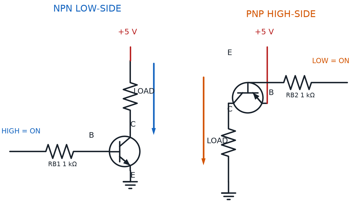
| Feature | NPN Transistor | PNP Transistor |
|---|---|---|
| Layer order | N-type / P-type / N-type | P-type / N-type / P-type |
| Turns on when | Current flows into the base | Current flows out of the base |
| Current direction | Collector to emitter | Emitter to collector |
| Symbol arrow | Points outward, away from base | Points inward, toward base |
| Used in this course's kit | Yes — BC547, 2N2222 | No |
That symbol arrow is worth remembering on its own. Every transistor schematic symbol has a small arrow on the emitter lead, and that one arrow tells you everything about which family you're looking at and which way current flows.
The Arrow Never Lies
 If a transistor symbol's arrow points away from the base, it's NPN. If it points toward the base, it's PNP. That single arrow is faster to check than memorizing the whole layer sandwich every time.
Transistor Switching: A Small Current Controls a Big One
The simplest job a transistor can do is act like a switch — but a switch with no moving parts, flipped entirely by current instead of by a finger. Transistor switching is the use of a transistor's base current to turn the larger collector-to-emitter current fully on or fully off, the same way a light switch turns a lamp fully on or fully off.
Picture a breadboard circuit with an NPN transistor's collector wired through a resistor to an LED, and the LED wired up to the positive supply. The emitter goes straight to ground. With no current flowing into the base, the transistor blocks the collector-to-emitter path completely, and the LED stays dark. The instant enough current flows into the base — even a tiny trickle from a button press through a resistor — the transistor opens that path, and the LED lights up. Removing the base current shuts the LED back off, instantly.
Try that exact circuit yourself in the sim below. Flip the base switch on and off, then watch what happens to the collector current and the LED.
Diagram: Transistor as a Switch — Breadboard Demo
Transistor as a Switch — Breadboard Demo
Type: microsim
sim-id: transistor-switch-breadboard-demo
Library: p5.js
Status: Specified
Purpose: Let students flip a small base-current switch on and off in a rendered breadboard circuit and directly observe how that tiny current controls a much larger collector current lighting an LED, while also identifying the base, collector, and emitter leads and seeing the transistor's cutoff and saturation states.
Bloom Taxonomy: Understand (L2) / Apply (L3). Bloom Verb: demonstrate, predict, identify.
Learning objective: Given a rendered breadboard circuit with an NPN transistor, a base-current push button, a base resistor, and a collector LED, predict and observe whether the LED lights when the base switch is open (cutoff) versus closed (saturation), and identify the base, collector, and emitter leads on the rendered part.
Reuse check: An embeddings search (find-similar-templates, mode=reuse) for "Title: Transistor as a Switch Breadboard Demo | Topic: NPN transistor base current controlling collector current to an LED, transistor switching, saturation and cutoff | Subjects: Electronics, Beginning Electronics | Grade Level: Junior High | Learning Objectives: Demonstrate how a small base current switches a much larger collector current on and off in a breadboard transistor circuit" returned a top match of "LED Dimmer Circuit" (dmccreary/moving-rainbow, WHAT score 0.6394, recommendation "template") — in the 0.60-0.75 template band, but built around PWM brightness dimming rather than a base-switches-collector breadboard circuit, and from a Mathematics-tagged repo rather than Electronics. The second match, "Breadboard" (dmccreary/microsims, 0.6093, "template"), is a generic empty breadboard renderer with no transistor logic. Given the topical mismatch, this is written as a new specification rather than a reuse, noting the LED Dimmer Circuit and the generic Breadboard sim as loose structural templates. This is an excellent fit for the breadboard-sim-generator skill, and should extend this repository's existing breadboard-lib.js (already used by button-led-breadboard and light-dark-detector in Chapters 7 and 17) with a rendered TO-92 transistor component.
Canvas layout: Main area shows a rendered half breadboard with a battery pack, an NPN transistor (TO-92 package, flat side visible, three labeled leads), a base resistor, a push-button base switch, and a collector-side LED with its own resistor; right side panel holds a "Base Switch: ON/OFF" toggle button, an NPN/PNP mode toggle, and an infobox.
Components/elements involved: A rendered breadboard with power and ground rails; a battery pack; a TO-92 transistor with base, collector, and emitter leads individually labeled and hoverable; a base resistor and push-button switch feeding the base; a collector resistor and LED; connecting wires; an animated current-flow indicator showing a thin trickle on the base wire and a thick flow on the collector-emitter path when conducting.
Required interactivity: - Clicking the "Base Switch" button toggles base current on or off; when on, animated current flows into the base, the transistor's internal path opens, thick animated current flows collector-to-emitter, and the LED lights at full brightness (saturation); when off, no base current flows, the collector path is blocked, and the LED stays dark (cutoff) - Hovering the base, collector, or emitter lead opens an infobox naming that lead and stating its role, reinforcing the base/collector/emitter definitions from the chapter text - Toggling NPN/PNP mode redraws the transistor's schematic symbol arrow and flips the current direction and switch polarity, reinforcing the NPN vs. PNP comparison table - Button "Reset" returns to the default off (cutoff) state with NPN mode selected
Default state: NPN mode, base switch off, transistor in cutoff, LED dark, infobox reads "Cutoff — no base current, no collector current. The transistor acts like an open switch."
Data Visibility Requirements: Stage 1: Show whether the base switch is open or closed Stage 2: Show the resulting operating state label ("Cutoff" or "Saturation") Stage 3: Show the animated current on the base wire (thin, on/off) versus the collector-emitter path (thick, on/off) Stage 4: Show the LED's lit/dark state matching the collector current
Instructional Rationale: An Understand/Apply "demonstrate/predict" objective calls for a manipulable breadboard simulation with a clear before-and-after state, so students directly connect a tiny base current to a much larger collector current rather than reading the relationship as an abstract statement.
Color scheme: Thin green current-flow dots on the base wire, thick green current-flow dots on the collector-emitter path when conducting, gray and dim when off, consistent with the palette used in Chapter 12's diode bias demo.
Responsive behavior: Breadboard view and the control/infobox panel stack vertically on narrow screens; the Base Switch and NPN/PNP toggle buttons remain full-width and touch-friendly.
Implementation: p5.js, built using the breadboard-sim-generator skill's rendered tie-point approach, extending this repository's existing breadboard-lib.js with a new transistor component and base-switch logic.
That sim shows two important extremes, and both extremes have names. Transistor cutoff is the operating state where base current is too small — essentially zero — for any collector-to-emitter current to flow at all, so the transistor behaves like an open switch. Transistor saturation is the opposite operating state, where base current is high enough that the transistor is fully "on," letting through as much collector-to-emitter current as the rest of the circuit allows, behaving like a closed switch with almost no resistance at all.
Between those two extremes sits a third state that the next section explores in detail — one where the transistor isn't fully open or fully closed, but somewhere in between.
- Cutoff — base current ≈ 0, collector current = 0, transistor acts like an open switch
- Active region — base current is small but present, collector current is proportional to it (this is where amplification happens)
- Saturation — base current is large enough that collector current maxes out, transistor acts like a closed switch
Don't Mix Up the Leads
 Plugging a transistor into a breadboard backward — swapping the collector and emitter, or missing the base entirely — is one of the most common beginner mistakes. Always check the transistor's flat side and its datasheet pinout before wiring, the same careful habit Chapter 12 taught you for a diode's band marking.
Transistor Amplification: The Active Region at Work
Switching only uses a transistor's two extreme states — fully off or fully on. The middle ground, the active region mentioned above, is where a transistor does something even more powerful.
Transistor amplification is the use of a small change in base current to produce a proportionally larger change in collector current, letting a weak signal control a much stronger one without the two ever mixing together. A microphone's tiny electrical signal, boosted by a chain of transistors until it's strong enough to drive a loudspeaker, is amplification at work — the exact same physics as switching, just used to scale a signal up smoothly instead of snapping it fully on or off.
That scaling factor has a name and a simple formula. Every transistor has a current gain, often labeled hFE on a datasheet, that tells you how many times bigger the collector current is than the base current that's controlling it.
Current Gain (Amplification) Formula
where:
- \( I_C \) is the collector current
- \( I_B \) is the base current
- \( \beta \) (also written hFE on a datasheet) is the transistor's current gain
Try the math yourself: a BC547 with an hFE of about 100, fed a base current of 1 milliamp (0.001 A), predicts a collector current of \( I_C = 100 \times 0.001 = 0.1 \) A — exactly 100 milliamps, which happens to be right at the BC547's maximum rating. That's not a coincidence real circuits ignore; it's exactly why base resistors are chosen carefully, to keep collector current safely under a transistor's limit instead of right at the edge of it.
Explore the gain formula yourself, and compare how the BC547 and 2N2222 respond to the exact same base current, in the sim below.
Diagram: Transistor Current Gain Explorer
Transistor Current Gain Explorer
Type: microsim
sim-id: transistor-current-gain-explorer
Library: p5.js
Status: Specified
Purpose: Let students adjust a base current slider and watch the resulting collector current calculated live using the current gain formula, comparing the BC547 and 2N2222's different typical gain values and seeing where each transistor's collector current caps out at saturation.
Bloom Taxonomy: Apply (L3). Bloom Verb: calculate, demonstrate, compare.
Learning objective: Given a base current value and a selected transistor (BC547 or 2N2222), calculate the resulting collector current using \( I_C = \beta \times I_B \), and compare how the two transistors' different gain and current-rating values change that outcome.
Reuse check: An embeddings search (find-similar-templates, mode=reuse) for "Title: Transistor Current Gain and Saturation Cutoff Explorer | Topic: Transistor amplification, current gain, saturation region, cutoff region, base current versus collector current | Subjects: Electronics, Beginning Electronics | Grade Level: Junior High | Learning Objectives: Predict how changing base current moves an NPN transistor between cutoff, active amplification, and saturation regions" returned a top match of "Transistor Driver and Dimmer Circuit" (dmccreary/moving-rainbow, WHAT score 0.5391, recommendation "generate") — below the 0.60 template threshold. That sim teaches duty-cycle LED dimming through a transistor rather than the current-gain formula and BC547/2N2222 comparison this chapter needs, so its objective does not transfer. This is a new specification.
Canvas layout: Left side shows a base-current slider (0-2 mA) and a transistor selector (BC547 / 2N2222); right side shows a live bar comparing base current (thin bar) to calculated collector current (thick bar), the gain formula with current numbers substituted in, and an infobox.
Components/elements involved: A base-current slider; a BC547/2N2222 selector; a live numeric readout of hFE, base current, and calculated collector current; a two-bar comparison chart (base current vs. collector current, drawn at very different scales to emphasize the amplification); a saturation warning indicator.
Required interactivity: - Dragging the base-current slider recalculates collector current live using \( I_C = \beta \times I_B \) for the selected transistor's typical hFE, and updates both bars and the formula readout with the substituted numbers - Selecting BC547 or 2N2222 changes the hFE used in the calculation and the maximum collector-current rating shown, so the same base current produces a different predicted collector current for each part - When the calculated collector current would exceed the selected transistor's maximum rating, the collector bar flashes red and the infobox explains that the transistor has reached saturation and cannot supply more current no matter how much higher the base current climbs - Hovering the formula or either bar opens an infobox explaining that term in plain language - Button "Reset" returns to a base current of 0.5 mA with the BC547 selected
Default state: BC547 selected, base current at 0.5 mA, hFE shown as 100, calculated collector current readout "50 mA," both bars drawn at their respective heights, infobox reads "Active region — collector current is proportional to base current."
Data Visibility Requirements: Stage 1: Show the selected transistor's hFE value Stage 2: Show the current base-current value from the slider Stage 3: Show the formula with those exact numbers substituted in Stage 4: Show the calculated collector current as both a number and a bar height, next to the base-current bar for scale comparison
Instructional Rationale: An Apply-level "calculate/compare" objective calls for a parameter-exploration pattern with the formula's substituted values always visible, so students see the arithmetic happen rather than only the final answer, and directly compare how gain and current rating change the outcome between the two named transistors.
Color scheme: Thin blue bar for base current, thick orange bar for collector current (echoing the "small controls big" idea), red flash for the saturation warning, consistent with this chapter's other diagrams.
Responsive behavior: The slider/selector panel and the bar-chart/infobox panel stack vertically on narrow screens; the slider remains full-width and touch-draggable.
Implementation: Plain p5.js, not the breadboard-sim-generator — this is a calculator-style parameter explorer rather than a wired circuit, matching the standalone decoder pattern used by this book's other component-comparison sims.
You Don't Need Datasheet Memory
 Base, collector, emitter, cutoff, saturation, gain — that's a lot of new vocabulary landing at once. You don't have to memorize exact hFE numbers. Knowing that gain exists, that it's different for every transistor, and that a datasheet always lists it, is more than enough for now.
Comparing the Course's Two Transistors: BC547 vs. 2N2222
This course's kit includes two different NPN transistors, and each earns its spot for a different reason. The BC547 transistor is a small, general-purpose NPN transistor in a compact TO-92 plastic case, rated for up to about 100 milliamps of collector current, which is plenty for switching a single LED or driving another transistor's base. The 2N2222 transistor is also an NPN part in a TO-92 case, but built to handle far more current — typically up to around 600 milliamps — making it the better choice whenever a project needs to switch a small DC motor, a buzzer, or several LEDs at once.
| Feature | BC547 | 2N2222 |
|---|---|---|
| Transistor type | NPN | NPN |
| Package | TO-92 | TO-92 |
| Typical max collector current | ≈ 100 mA | ≈ 600 mA |
| Typical current gain (hFE) | ≈ 110-800 | ≈ 100-300 |
| Best for | Switching a single LED or another transistor's base | Switching motors, buzzers, or multiple LEDs |
| Feels like, in this course | The precise scalpel | The reliable workhorse |
Both transistors share the exact same three-lead base/collector/emitter layout and the exact same NPN switching behavior — the only real difference that matters for choosing between them is how much collector current each one can safely handle. A project that only needs to light one LED barely notices the difference. A project that needs to spin a motor absolutely does.
The larger transistor family adds two important choices: the 2N3906 is PNP rather than NPN, and the metal-cased 2N3055 is a power device that needs deliberate thermal design. Package and pinout can vary by manufacturer, so always verify the exact datasheet before wiring any transistor.
Diagram: Five Common Transistor Types
Run the Five Common Transistor Types MicroSim fullscreen
From One Switch to Many: What's an Integrated Circuit?
Every transistor you've met so far does exactly one job: it's a single switch or a single amplifier, sitting alone in its own three-legged package. But real gadgets — phones, game controllers, even a blinking holiday light — need dozens, sometimes billions, of transistors working together to do anything useful. Wiring that many individual transistors by hand would be impossible.
An integrated circuit is a single small chip that packs many transistors, along with other components, into one sealed package to perform a much more complex job than any lone transistor could manage. Think of it as the difference between one light switch and an entire pre-wired control panel — the panel still uses switches underneath, just hundreds of them, already wired together and sealed inside one convenient case.
One Switch Becomes Many
Here's the big idea to hold onto: a transistor is one tiny switch, and an integrated circuit packs dozens or hundreds of those switches into a single chip so it can do far more. You've just spent this whole chapter mastering the building block — now meet two finished buildings made from it.
This course's kit includes two integrated circuits, and each one gets its own full chapter soon. For now, here's just enough to know what they are and why they're worth getting excited about.
Coming in Chapter 14: The 555 Timer IC
The 555 Timer IC is an integrated circuit built specifically to generate precise time delays or repeating pulses, using an internal network of resistors, comparators, and transistor switches working together. It's one of the most popular chips ever made, found inside blinking LED circuits, beeping alarms, and countless timing projects for the last fifty years.
A 555 timer can be wired to behave in two very different ways. 555 astable mode wires the chip so its output never settles into a stable state — it continuously switches high and low all on its own, producing a steady repeating pulse, perfect for blinking an LED or sounding a repeating tone. 555 monostable mode wires the chip so it has exactly one stable resting state — a trigger signal starts a single timed pulse of a set length, and then the output falls back to resting until triggered again, exactly like a "one-shot" kitchen timer.
Every 555 timer chip, no matter how it's wired, arrives with the exact same eight pins in the exact same positions. 555 Pin Configuration refers to that fixed arrangement of eight pins, each with its own defined role in shaping the chip's timing behavior.
| Pin | Name | Role |
|---|---|---|
| 1 | GND | Connects to the circuit's ground |
| 2 | TRIGGER | Starts a timing cycle |
| 3 | OUTPUT | Delivers the chip's high/low signal |
| 4 | RESET | Forces the output low when needed |
| 5 | CONTROL VOLTAGE | Fine-tunes internal timing thresholds |
| 6 | THRESHOLD | Ends a timing cycle |
| 7 | DISCHARGE | Drains the timing capacitor |
| 8 | VCC | Connects to the positive supply |
Chapter 14 will wire every one of those pins and walk through exactly how a resistor-capacitor network sets the chip's timing — for now, just knowing these eight pins exist, and that they always sit in the same spots, is enough.
Coming in Chapter 15: The 74HC595 Shift Register
The second chip in this course's kit solves a completely different problem: controlling a lot of outputs using only a few wires. A shift register is a digital integrated circuit that stores and moves a sequence of data bits one at a time, usually accepting them one bit at a time and then making them all available at once.
Picture a bucket brigade passing water buckets hand to hand down a line of people, one bucket at a time, until every person in line is holding one bucket. Then, on a signal, everyone tips their bucket out at exactly the same moment. That's exactly how a shift register handles data — and it's exactly what the 74HC595 shift register does with electrical bits instead of water buckets, taking data in one bit at a time and controlling eight separate output pins from just a few control wires.
Two terms describe the two halves of that bucket-brigade idea. Serial data input means sending data one single bit at a time, one after another, along a single wire, in sequence — the buckets moving down the line, one at a time. Parallel data output means presenting multiple bits of data all at the same moment, each one on its own separate wire, all available simultaneously — every person tipping their bucket out together.
- Serial data input — one bit at a time, one wire, in sequence (buckets moving down the line)
- Parallel data output — many bits at once, many wires, all at the same moment (everyone tipping together)
That serial-in, parallel-out trick is exactly what lets a 74HC595 control eight separate LEDs while using only a handful of wires from whatever is sending it data — a huge upgrade over wiring eight LEDs to eight completely separate control lines. Chapter 15 builds that circuit from scratch.
See both chips side by side, and preview what each one does, in the interactive diagram below.
Diagram: Two ICs Coming Soon — 555 Timer and 74HC595 Preview
Two ICs Coming Soon — 555 Timer and 74HC595 Preview
Type: infographic
sim-id: ic-preview-555-74hc595
Library: p5.js
Status: Specified
Purpose: Give students a light, survey-level preview of the 555 timer and 74HC595 shift register chips they will build with in Chapters 14 and 15, without teaching full wiring or timing formulas here.
Bloom Taxonomy: Remember (L1) / Understand (L2). Bloom Verb: identify, describe, summarize.
Learning objective: Identify the 555 timer IC and the 74HC595 shift register by their pin count and package shape, and summarize in one sentence each what job every chip will perform later in the course.
Reuse check: An embeddings search (find-similar-templates, mode=reuse) for "Title: Meet the ICs Coming Soon: 555 Timer and 74HC595 Shift Register | Topic: Integrated circuit survey introduction, 555 timer astable and monostable modes, 555 pin configuration, 74HC595 shift register serial data input and parallel data output | Subjects: Electronics, Beginning Electronics | Grade Level: Junior High | Learning Objectives: Identify the 555 timer IC and the 74HC595 shift register and summarize what each chip will be used for later in the course" returned two matches at "template" strength: "555 Timer" (dmccreary/microsims, WHAT score 0.6463) and "Shift Register MicroSim" (dmccreary/digital-electronics, WHAT score 0.6351). Both are full teaching simulations — the 555 Timer sim includes accurate RC timing formulas and a live waveform display, and the Shift Register sim includes a logic analyzer showing clock and latch timing — exactly the deep, formula-level content this chapter is intentionally deferring to Chapters 14 and 15. Reusing either sim here would duplicate those future chapters' central teaching tool before students have the RC-timing (Chapter 10) and clocked-logic background those sims assume. This is written as a new, deliberately shallow specification instead, and both existing sims are flagged here as the direct, ready-to-embed resources Chapters 14 and 15 should reuse when those chapters are generated.
Canvas layout: Two side-by-side chip panels on a single canvas — left panel shows an 8-pin DIP outline labeled "555 Timer," right panel shows a 16-pin DIP outline labeled "74HC595 Shift Register"; a small infobox sits below both panels.
Components/elements involved: A rendered 8-pin DIP chip silhouette; a rendered 16-pin DIP chip silhouette; a "Coming in Chapter 14" tag on the 555 panel; a "Coming in Chapter 15" tag on the 74HC595 panel; an infobox.
Required interactivity: - Clicking the 555 Timer chip panel reveals an infobox with one sentence on astable mode, one sentence on monostable mode, and the note "Full wiring and timing math in Chapter 14" - Clicking the 74HC595 chip panel reveals an infobox with one sentence on serial data input, one sentence on parallel data output, and the note "Full wiring and 8-LED project in Chapter 15" - Hovering either chip silhouette gives it a highlight border to show it is clickable - No sliders, waveforms, or timing simulation are included — this element is intentionally kept at preview depth
Default state: Neither panel expanded; infobox reads "Click a chip to preview what it does."
Data Visibility Requirements: Stage 1: Show each chip's name and pin-count package shape Stage 2: Show which future chapter teaches that chip in full Stage 3: On click, show the one or two teaser sentences for that chip
Instructional Rationale: A Remember/Understand "identify/summarize" objective at survey depth calls for a simple click-to-reveal pattern with short teaser text, not a manipulable simulation — matching this chapter's intentional choice to name and preview these chips without teaching their internal timing or clocking behavior, which belongs to Chapters 14 and 15.
Color scheme: Blue chip outlines matching the site's primary theme color, orange highlight border on hover matching the accent color, consistent with this chapter's other diagrams.
Responsive behavior: The two chip panels stack vertically on narrow screens instead of sitting side by side; the infobox remains full-width beneath them.
Implementation: Plain p5.js, not the breadboard-sim-generator — this is a lightweight click-to-reveal preview, not a wired or timed circuit.
Same Family, Bigger Job
Every time you see the word "chip" or "IC" from here on, remember it's built from the exact same idea you just mastered — transistors switching current — just a whole lot of them, wired together by the manufacturer instead of by you.
Chapter Summary: Key Takeaways
You've just learned the single idea that unlocks everything else this course builds toward:
- A transistor uses a small current at its transistor base to control a much larger current between its transistor collector and transistor emitter
- An NPN transistor turns on when current flows into its base; a PNP transistor turns on when current is pulled out — this course uses NPN only
- Transistor switching flips a transistor fully on (transistor saturation) or fully off (transistor cutoff), while transistor amplification uses the in-between active region to scale a small signal up smoothly
- The BC547 transistor handles smaller currents like a single LED; the 2N2222 transistor handles bigger currents like a motor or buzzer
- An integrated circuit packs many transistors into one chip to do far more than any single transistor could alone
- The 555 Timer IC generates timing pulses in 555 astable mode (repeating) or 555 monostable mode (one-shot), using its fixed eight-pin 555 pin configuration
- A shift register, like the 74HC595 shift register, takes a serial data input — one bit at a time — and turns it into a parallel data output — many bits at once, controlling many LEDs from just a few wires
Chapter 14 picks up right where this chapter left off, wiring a real 555 timer chip and calculating exactly how long its pulses last. Chapter 15 goes even further, chaining a 74HC595 shift register to a full row of eight LEDs and controlling every one of them from just three wires. You've built the foundation — next, you get to build with it.
Transistor Handler: Unlocked
 Huge milestone, builder — you can now explain how a transistor switches and amplifies, pick the right transistor for a job, and name two chips that are about to level up everything you build. That's the gateway concept of the whole course, mastered. Current's flowing your way — see you in Chapter 14!