Advanced Circuits and Your Capstone Project
Summary
The course's capstone chapter combines everything into named real-world projects — a busy board, a solar night light, an LED noodle costume — and walks students through planning, designing, prototyping, and demonstrating an original capstone project of their own.
Concepts Covered
This chapter covers the following 21 concepts from the learning graph:
- Flip Flop Circuit
- Memory Cell
- Bistable Circuit
- Timing Circuit
- Oscillator Circuit
- LED Flasher
- Signal Generator
- Multi-Stage Circuit
- Combining Sensor and Output
- Night Light Circuit
- Solar Night Light Project
- Busy Board Project
- LED Noodle Costume
- Capstone Project Planning
- Project Proposal
- Project Requirements List
- Circuit Block Diagram
- Original Circuit Design
- Prototype Iteration
- Project Demonstration
- Project Documentation
Prerequisites
This chapter builds on concepts from:
- 6. Meet Your Breadboard
- 7. Wiring Skills and Circuit Layout
- 10. Capacitor Timing and Resistor Values
- 13. Meet the Transistor
- 15. Shift Registers and IC Handling
- 16. Switches, Buttons, and Wired Logic
- 17. Sensing Light: Photoresistors and Dark Detectors
- 18. LEDs, RGB Color, and Motors
- 21. Systematic Troubleshooting
- 22. Batteries, Regulators, and Buck Converters
- 23. Signal Generators and Solar Power
- 25. NAND, NOR, XOR, and the RS Latch
Chapter 25 closed with a promise: flip-flops and memory cells were waiting in the wings, and a bigger project was waiting at the very end of the book. Both promises land right here — and this is the last stop. Every idea since Chapter 1 first asked how electricity works has been building toward this moment: enough shared vocabulary to describe combining circuits like a real engineer, and enough skill to design, build, and show off a project that's entirely your own.
This chapter comes in two parts. The first is short — a handful of new words that name patterns you've already built, so "timing circuit," "oscillator," and "multi-stage circuit" stop sounding like jargon and start sounding like things on your breadboard right now. The second part is the main event: the real, repeatable process for planning an original capstone project, from a rough idea to a finished demonstration.
The Last Chapter — And Your Biggest Build Yet
 Welcome to the finale, builder! This is the last chapter in the book, and it's the one every single earlier chapter was quietly training you for. You're not here to learn one more part — you're here to design something nobody has ever built before: your own original circuit. Let's light it up, one last time!
One Latch, Many Names: Flip-Flops, Memory Cells, and Bistable Circuits
The cross-coupled NAND circuit you wired up in Chapter 25 already earned itself a name — an RS latch. It turns out that same circuit, and every circuit like it, also answers to three bigger, more general names, depending on how far you zoom out.
A Flip Flop Circuit is any circuit that stores exactly one bit of information and holds it steady until a specific input tells it to change — the RS latch you built is the simplest possible example, and it's why Chapter 25 called it "the course's only taste of digital memory." A Memory Cell is a flip-flop circuit used specifically for its storage job, as one small piece of a much larger memory system — every single bit stored inside a real computer's RAM chip is, underneath layers of extra engineering, a slightly more sophisticated cousin of the exact RS latch you already wired.
Both of those words describe circuits that remember something. The word that describes why they can remember anything at all is more general still. A Bistable Circuit is any circuit with exactly two stable output states that it holds onto on its own, without any additional input needed to keep it there — "bi" for two, "stable" for staying put. An RS latch and a flip-flop circuit are both examples of a bistable circuit; a bistable circuit is the general shape, and they're two specific ways of building it.
- Bistable Circuit — the general idea: any circuit with two states it holds onto by itself
- Flip Flop Circuit — a bistable circuit built specifically to store one bit, controlled by defined inputs
- Memory Cell — a flip-flop circuit used as one unit inside a larger memory system, like RAM
Why So Many Words for One Circuit?
 It might seem strange that one circuit earns three names — RS latch, flip-flop, memory cell, all bistable. But engineers zoom in and out all the time. "Bistable" describes the behavior. "Flip-flop" describes the job. "Memory cell" describes the role it plays inside something bigger. Same circuit, three honest answers depending on the question being asked.
If you want to watch a bistable circuit hold its memory one more time, scroll back to Chapter 25's cross-coupled NAND simulator — press Set, let go, and notice the state doesn't drift back on its own. That's every word on this page, in action.
Naming the Pattern: Timing, Oscillators, and Signal Shaping
Chapter 14's 555 timer and Chapter 23's XR2206 kit can look like two completely different chips at first glance. A little more vocabulary shows they're really doing the same small handful of jobs, just dressed up differently.
A Timing Circuit is any circuit whose job is to produce a precise, predictable delay or repeating interval — built from a resistor-capacitor network (Chapter 10) or a dedicated chip like the 555 (Chapter 14). An Oscillator Circuit is a timing circuit that keeps repeating forever on its own, with no fresh trigger needed for each new cycle — the 555's astable mode from Chapter 14 and the XR2206's continuous wave output from Chapter 23 are both oscillator circuits, even though one blinks and the other draws smooth curves on a scope.
The most familiar oscillator circuit in this entire course deserves its own name too. An LED Flasher is an oscillator circuit wired specifically so its repeating output blinks an LED on and off — the very first 555 astable project you built back in Chapter 14 was an LED flasher, and it's the simplest possible proof that an oscillator circuit is actually doing something. Zoom out one more level, and a Signal Generator is any device or circuit built specifically to produce a chosen, controllable waveform on demand — the XR2206 kit is a signal generator with knobs for shape, frequency, and amplitude, but so, in a much simpler one-shape-only sense, is a single 555 timer set to a fixed square wave.
Diagram: RC Timer, 555 Oscillator, and Signal Generator
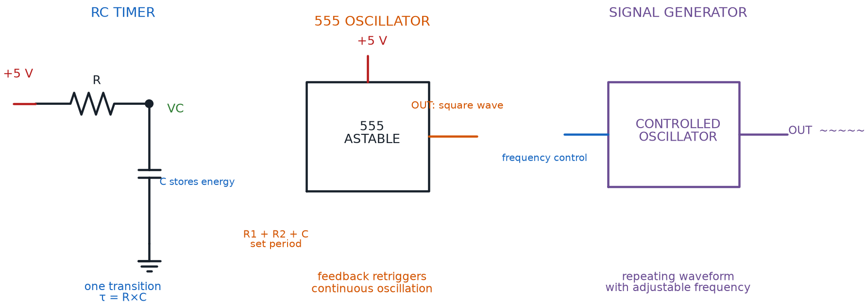
Here's how all four words line up against circuits you've already built with your own hands.
| Term | What It Names | Circuit You Already Built | Chapter |
|---|---|---|---|
| Timing Circuit | Any circuit producing a precise delay or interval | An RC charge-and-discharge circuit | 10 |
| Oscillator Circuit | A timing circuit that repeats forever, unprompted | A 555 timer in astable mode | 14 |
| LED Flasher | An oscillator circuit whose output blinks an LED | Your first 555 astable LED project | 14 |
| Signal Generator | A device that produces a chosen waveform on demand | The XR2206 sine/square/triangle kit | 23 |
Chaining Blocks Together: Multi-Stage Circuits
Most projects so far in this course have been a single idea wired up once. Real projects — including the one you're about to design — almost always chain several ideas together, one stage feeding the next.
A Multi-Stage Circuit is any circuit built from two or more of these building blocks wired in sequence, so one stage's output becomes the very next stage's input. Chapter 17's dark detector was already a multi-stage circuit and you may not have noticed: a sensor stage (the photoresistor voltage divider) fed a switching stage (the transistor), which fed an output stage (the LED). That exact shape — sensor, then control, then output — is common enough to earn its own name.
Combining Sensor and Output is the general design pattern of wiring any input sensor stage into any output stage, almost always through a control, logic, or timing stage in between that decides when the output should respond. A push button feeding a 555 timer's trigger pin, which fires a buzzer, is combining sensor and output. A photoresistor feeding a transistor switch, which lights an LED, is combining sensor and output. Once you can name the three stages — sensor, control, output — you can describe almost any project in this book in one sentence.
Test Every Stage Alone First
 Before you wire three stages together, build and test each one by itself. Confirm the sensor stage reads correctly on its own. Confirm the output stage lights up when you touch it directly to power. Chapter 21's systematic troubleshooting habit — change one thing, test, repeat — gets far easier when you already know each individual stage works before you ever connect them.
Try assembling your own multi-stage circuit in the sim below — drag a sensor block, a control block, and an output block into place, and watch a signal actually flow from one stage to the next.
Diagram: Sensor-Logic-Output Block Diagram Builder
Sensor-Logic-Output Block Diagram Builder
Type: microsim
sim-id: sensor-logic-output-block-builder
Library: p5.js
Status: Specified
Purpose: Let students drag a sensor block, a control/logic/timing block, and an output block into a horizontal chain, then watch an animated signal travel from stage to stage — directly demonstrating the Multi-Stage Circuit and Combining Sensor and Output concepts before students use this same block-diagram thinking to plan their own capstone project.
Bloom Taxonomy: Apply (L3). Bloom Verb: construct, arrange, demonstrate, predict.
Learning objective: Given a palette of sensor blocks (button, photoresistor, potentiometer), control blocks (transistor switch, 555 timer, shift register), and output blocks (LED, motor, buzzer), arrange one of each into a connected three-stage chain and predict, then verify, how the sensor's state propagates through the control stage to change the output.
Reuse check: An embeddings search (find-similar-templates, mode=reuse) for "Title: Sensor to Output Block Diagram Builder | Topic: circuit block diagram, multi-stage circuit, combining sensor and output, timing circuit, oscillator circuit | Subjects: Electronics, Electric Circuits | Grade Level: Junior High | Learning Objectives: Given draggable sensor, logic/timing, and output blocks, arrange them into a working multi-stage circuit block diagram and observe simulated signal flow from input to output" returned a top match of "Standard Feedback Control Loop Block Diagram" (dmccreary/control-systems, WHAT score 0.5408, recommendation "generate") — below the 0.60 template threshold, and a High School/Undergraduate Control Systems sim about closed-loop feedback theory, not a breadboard-style sensor/output chain a junior-high builder would recognize from their own kit. A keyword search of the 3,764-entry catalog for "block diagram," "multi-stage," and "sensor output" surfaced no closer electronics match. New specification. Library/Implementation fit: an excellent, central candidate for the breadboard-sim-generator skill — each draggable block renders using this repository's existing component functions (bbPhotoresistor(), bbTransistor(), bbLED(), and similar) from breadboard-lib.js, and the animated current-dot signal path reuses the same current-flow-along-a-completed-path pattern specified for Chapter 24's and Chapter 25's gate sims — just generalized from fixed transistor gates to a student-chosen chain of any three blocks.
Canvas layout: A horizontal three-slot chain area across the top (Sensor slot, Control slot, Output slot, connected by wire segments) with a block palette below it holding draggable icons: three sensor blocks (push button, photoresistor, potentiometer), three control blocks (transistor switch, 555 timer, shift register), and three output blocks (LED, small motor, buzzer); a small infobox sits to the right.
Components/elements involved: Three empty labeled slots with placeholder outlines; nine draggable block icons in the palette below, each a simplified breadboard-style rendering of the real component; connecting wire segments between filled slots; an animated signal dot; an infobox panel.
Required interactivity: - Dragging any sensor block into the Sensor slot, any control block into the Control slot, and any output block into the Output slot completes the chain and enables a "Run Signal" button - Clicking "Run Signal" animates a colored dot traveling from the sensor block through the control block to the output block, and the output block visibly activates (LED lights, motor spins, buzzer icon pulses) only if the chosen sensor's simulated state currently satisfies the control block's condition - A toggle or slider on the currently placed sensor block (press the button, slide light level, turn the pot) lets students change the sensor's state and immediately see whether the output responds, without re-dragging anything - Hovering any block, filled or in the palette, opens an infobox naming the block, which chapter first introduced it, and one real project that uses it (e.g., "Photoresistor — Chapter 17's dark detector uses this as its sensor stage") - Clicking a "Try a Preset" button loads one of three preset chains — dark detector, 555-triggered buzzer, button-driven shift register pattern — showing students working examples before they build their own combination
Default state: All three slots empty; palette fully visible; infobox reads "Drag one block into each slot — sensor, control, output — then press Run Signal."
Instructional Rationale: An Apply-level "construct/arrange/predict" objective needs a manipulable chain with an immediate, checkable consequence. Letting students choose freely among three sensor, three control, and three output blocks — rather than watching one fixed example — reinforces that Multi-Stage Circuit and Combining Sensor and Output are general patterns that fit many different real parts, not one specific wiring.
Color scheme: Same green current-flow dots and dim gray off-state used throughout this book's transistor and gate sims; blue outline on the slot currently accepting a drag; amber highlight on the active preset button.
Responsive behavior: The three-slot chain stacks vertically on narrow screens with vertical connecting wires; the block palette wraps into a scrollable row of icons; the infobox moves below the chain.
Implementation: p5.js, built on the breadboard-sim-generator skill's rendered-component approach, reusing breadboard-lib.js component-drawing functions and the animated current-path pattern from this book's transistor gate sims, extended with a simple drag-and-drop slot system.
That block-diagram thinking — sensor stage, control stage, output stage — is exactly the tool you'll use in a few pages to plan a project of your own. First, though, meet three builders who already used it.
Three Builders, Three Projects: Meet Your Capstone Inspiration
Designing a project from a completely blank page is hard, even for experienced engineers. It's much easier to start from a real example, borrow the parts that fit, and change the rest. This course names three capstone projects as inspiration — not a menu you have to pick from, but proof of what's possible with exactly the parts in your kit.
All three share one ancestor concept worth naming first. A Night Light Circuit is any circuit built specifically as a finished, standalone project whose purpose is turning on a light automatically when it gets dark — in other words, Chapter 17's dark detector, packaged as a complete little product instead of a demo circuit on a breadboard.
The Solar Night Light Project takes that idea one step further: a night light circuit powered entirely by a solar panel and rechargeable battery, using the exact charging circuit from Chapter 23 — blocking diode, TP4056-style module, overcharge protection — so it needs no wall outlet and no disposable batteries, ever. By day, sunlight refills the battery; by night, the same Chapter 17 threshold behavior switches the light on by itself. See the Solar Night Light kit page for a full circuit diagram.
The Busy Board Project takes the multi-stage thinking from earlier in this chapter and multiplies it: one board covered with several independent multi-stage circuits — buttons, a dimmer potentiometer, a photoresistor trigger, an LED noodle strip — each its own small cause-and-effect demo a younger builder can explore by touch. Every interactive element must stay at a safe 3-to-5-volt low voltage, with every component securely enclosed so curious fingers never reach bare wiring. See the Busy Board kit page for the full component and safety guide.
The LED Noodle Costume takes the opposite approach — one flexible, wearable output instead of many small boards. An LED noodle is a flexible strip packed with tiny LEDs, costs about a dollar or two, and runs on just 3 volts DC while handling up to 100 milliamps — perfect for weaving into a costume or hat brim. A Chapter 13 2N2222 transistor switches or dims it safely; a potentiometer on its base turns that switch into a smooth brightness dial, the same pattern Chapter 17's LED dimmer used. See Lab 40 for the full wiring and brightness-control circuit.
The table below lines all three up side by side, so you can compare what each one asks of a builder.
| Project | Difficulty | Core Parts | Skills It Reuses | Best Fit For |
|---|---|---|---|---|
| Solar Night Light | Moderate | Photoresistor, solar panel, TP4056 charge module, LiPo battery, blocking diode, LED | Dark detector (Ch. 17), transistor switching (Ch. 13), solar charging (Ch. 23) | A builder who wants a "set it and forget it" outdoor gadget |
| Busy Board | Moderate to advanced | Buttons, switches, potentiometer, photoresistor, LED noodle, one or more transistors | Wired logic (Ch. 16), transistor dimming (Ch. 13), several multi-stage circuits on one board | A builder who wants to combine many small circuits into one gift-worthy board |
| LED Noodle Costume | Beginner to moderate | LED noodle (3 V, up to 100 mA), 2N2222 transistor, potentiometer, battery pack | Transistor switching (Ch. 13), current-limiting, wearable wiring | A builder who wants a wearable showpiece for a costume or performance |
Diagram: Capstone Project Inspiration Explorer
Run the Capstone Project Inspiration MicroSim fullscreen
Your Own Original Project: The Capstone Process
Whatever you decide to build, the same repeatable process that professional engineers use can carry any idea from a rough thought to a finished, demonstrated project. This is where every skill in this course finally gets to work together at once.
Capstone Project Planning is the umbrella term for the entire structured process of turning a project idea into a finished, demonstrated build — from a first written proposal all the way through the documentation you hand off at the end. It has eight stages, and you can start the first one right now, before you touch a single wire.
Diagram: Capstone Project Planning Workflow
Capstone Project Planning Workflow
Type: workflow
sim-id: capstone-project-planning-workflow
Library: p5.js
Status: Specified
Purpose: Give students a clickable map of the entire eight-stage capstone process — Capstone Project Planning as the umbrella, then Project Proposal, Project Requirements List, Circuit Block Diagram, Original Circuit Design, Prototype Iteration, Project Demonstration, and Project Documentation in sequence — so they can see the whole shape of the process before working through each stage in the chapter text below.
Bloom Taxonomy: Understand (L2) / Apply (L3). Bloom Verb: explain, interpret, apply.
Learning objective: Given a horizontal flowchart of the eight capstone project stages, click each stage to reveal what a builder produces at that stage and how it feeds the next one, then apply the sequence while planning an original project.
Reuse check: An embeddings search (find-similar-templates, mode=reuse) for "Title: Capstone Project Planning Workflow | Topic: project proposal, project requirements list, circuit block diagram, original circuit design, prototype iteration, project demonstration, project documentation | Subjects: Electronics, Electric Circuits, Engineering Design | Grade Level: Junior High | Learning Objectives: Given the stages of an original electronics capstone project, click each stage of the design process to reveal what that stage requires and produces" returned a top match of "Project Design Process Flowchart" (dmccreary/learning-micropython, WHAT score 0.7018, recommendation "template") — above the 0.60 template threshold, and a meaningful precedent since it comes from this course's own companion book. However, its seven steps include a "code structure" planning stage, which does not apply here: this course's own description explicitly places "microcontrollers, programming, or coding of any kind" under Topics Not Covered. Treated as an informing precedent rather than a direct reuse — adapted into an eight-stage, code-free sequence ending in Project Documentation instead of code planning. Two lower-scoring candidates, "Capstone Project Workflow" (dmccreary/blockchain, 0.6557, tagged High School Geometry — rejected as a clear subject mismatch despite the score) and "Capstone Project Component Map" (dmccreary/organizational-analytics, vis-network, 0.6402, a non-sequential concept map rather than an ordered process) were also reviewed and set aside. Library/Implementation fit: a strong candidate for the breadboard-sim-generator skill's supporting infrastructure, following this book's established Type: workflow clickable-node pattern with an infobox per node, rather than the tie-point breadboard rendering used for circuit-specific sims.
Canvas layout: A horizontal flowchart of eight labeled stage boxes connected by arrows, left to right: Project Proposal → Project Requirements List → Circuit Block Diagram → Original Circuit Design → Prototype Iteration (drawn with a small looping arrow back onto itself) → Project Demonstration → Project Documentation, with "Capstone Project Planning" labeling the whole chain as a bracket above all eight boxes; an infobox panel sits below the flowchart.
Components/elements involved: Eight stage boxes with icons (a pencil for Proposal, a checklist for Requirements List, three connected squares for Block Diagram, a schematic icon for Original Circuit Design, a looping arrow for Prototype Iteration, a spotlight icon for Demonstration, a folder icon for Documentation); connecting arrows; an overhead bracket labeled "Capstone Project Planning"; an infobox panel.
Required interactivity: - Clicking any stage box highlights it, opens an infobox naming the stage, describing what a builder produces there, and naming which stage's output feeds into it as input - Clicking the looping arrow on Prototype Iteration opens an infobox explaining that this is the one stage meant to repeat multiple times before moving on - A "Walk Me Through It" button auto-advances through all eight stages in order, pausing 3 seconds on each with its infobox open, for students who want a guided first pass - Hovering the "Capstone Project Planning" bracket opens an infobox defining it as the umbrella term for the whole eight-stage process
Default state: No stage selected; infobox reads "Click Project Proposal to start — or press Walk Me Through It for a guided tour of all eight stages."
Instructional Rationale: An Understand/Apply-level objective needs the whole process visible as one connected shape before a learner commits time to any single stage — a clickable flowchart lets students preview all eight stages, then return to this diagram as a checklist while they actually plan their own project stage by stage.
Color scheme: A single accent color washing left to right across the eight boxes (cool blue at Proposal, warming toward orange at Documentation) to suggest forward progress; the Prototype Iteration box's looping arrow highlighted in a distinct green to signal "repeat me."
Responsive behavior: The eight-box chain stacks into a vertical flow on narrow screens, arrows rotating to point downward; the infobox moves below the chain and stays legible at any width.
Implementation: p5.js, using this book's established clickable-node-with-infobox pattern for Type: workflow diagrams, with a simple auto-advance timer driving the optional guided tour.
Stage 1: Project Proposal
A Project Proposal is a short written or spoken description of what you intend to build and why, written before any wiring starts, so your goal is completely clear before you spend a single minute on a breadboard. A strong proposal answers three questions in just a few sentences: what will it do, who or what is it for, and which parts from your kit will it use?
Small and Finished Beats Big and Half-Built
A proposal for "a night light that turns on in the dark" is a project you can actually finish and demonstrate. A proposal for "a smart home system that controls everything" is a project that rarely gets past the wiring stage. Pick something small enough to finish, and you can always add features once it works.
Stage 2: Project Requirements List
A Project Requirements List is an itemized list of exactly what a finished project must do, which parts it will use, and how you'll know it's actually working — written down before the design starts, so nothing important gets forgotten once the building gets exciting. Fill in the template below with your own project's answers before moving any further.
My Capstone Project Requirements List
- Project name: _________
- One-sentence purpose (what problem does it solve?): _________
- Input(s) it will sense (button, photoresistor, potentiometer, other): _________
- Output(s) it will produce (LED, motor, buzzer, LED noodle): _________
- Power source (battery pack, USB supply, solar panel): _________
- Must-have feature #1: _________
- Must-have feature #2: _________
- Nice-to-have feature (only if time allows): _________
- Parts needed from your kit: _________
- Success test — "I'll know it works when...": _________
Stage 3: Circuit Block Diagram
A Circuit Block Diagram is a simple sketch showing a project's stages as labeled boxes — sensor, control, output — connected by arrows for signal flow, without worrying yet about specific resistor values or exact wiring. This is exactly the sensor-control-output thinking the block diagram builder sim taught you earlier in this chapter, now used as a genuine planning tool. Open that sim again, or just grab a pencil and paper, and sketch your own project's boxes the same way, before it becomes an actual circuit on a breadboard.
Stage 4: Original Circuit Design
An Original Circuit Design is the step where a block diagram's labeled boxes become an actual set of chosen real parts and a real wiring plan — which specific resistor value, which transistor, which capacitor, drawn from everything you've learned across this entire course. This is genuinely the most creative stage of the whole process, because it's where every single earlier chapter becomes a tool you get to pick up and use on purpose.
Check Every Rating Before You Combine Parts
 Combining stages is exactly where beginners get burned — sometimes literally. An LED noodle can safely take up to 100 milliamps at 3 volts, but a motor can pull far more current than that same transistor can handle. Before wiring any two blocks together, check every part's voltage and current rating, the same habit Chapter 22's current capacity check and Chapter 19's motor-driving lessons already taught you. Verify, don't assume.
Stage 5: Prototype Iteration
Prototype Iteration is the repeating cycle of building a rough first version of your design on a breadboard, testing it, noticing exactly what doesn't work, and rebuilding an improved version — repeated as many times as it takes, using the systematic troubleshooting habits from Chapter 21 at every pass. Build, test, note what failed, rebuild — then do it again.
Your First Prototype Won't Be Perfect — and That's Normal
 Every single circuit you've ever built in this course, including your teacher's demo boards and even Volt's own reference builds, needed at least one round of troubleshooting the first time. A prototype that doesn't work on the first try isn't a failure — it's Prototype Iteration doing exactly its job. Change one thing, test again, and keep going. This is what real engineering actually feels like.
Stage 6: Project Demonstration
A Project Demonstration is the planned act of showing your finished project working in front of an audience — classmates, family, a science fair judge — while explaining what each stage does and why, not just switching it on and quietly walking away. A great demonstration walks the audience through your own circuit block diagram out loud: "this sensor stage detects darkness, this control stage decides when to react, and this output stage is the payoff."
Stage 7: Project Documentation
Project Documentation is the finished written and photographed record of your project — its requirements list, its block diagram, a parts list, and a short explanation of how it works — kept so that you, or anyone else, could understand or rebuild the project later. Some builders choose to move a finished, working prototype onto a permanent perfboard (Chapter 8) at this stage, trading breadboard flexibility for a sturdier, more portable build worth keeping.
Before you call a project finished, make sure your documentation includes everything on this list.
- Project name and one-sentence purpose
- Final circuit block diagram
- Parts list with specific values (resistor ohms, capacitor µF, transistor model)
- A photo or clear sketch of the finished, working build
- One thing you'd improve if you built it again
Chapter Summary: Key Takeaways
This is the last "Key Takeaways" list in the entire course, so it earns a wider lens than usual — this is where every chapter you've read finally adds up.
- A Bistable Circuit is the general idea behind a Flip Flop Circuit and a Memory Cell — two stable states, held without help, the same trick your RS latch pulled off back in Chapter 25
- A Timing Circuit becomes an Oscillator Circuit when it repeats forever, an LED Flasher is the simplest oscillator circuit you can build, and a Signal Generator produces whatever waveform you dial in — all four words describe circuits you already built in Chapters 10, 14, and 23
- A Multi-Stage Circuit chains blocks together, and Combining Sensor and Output names the sensor-control-output shape behind almost every real project in this book, including Chapter 17's dark detector
- A Night Light Circuit, a Solar Night Light Project, a Busy Board Project, and an LED Noodle Costume are four real, buildable examples — inspiration for your own project, not a menu you're required to choose from
- Capstone Project Planning ties eight real stages together: a Project Proposal states your goal, a Project Requirements List pins down the details, a Circuit Block Diagram sketches the shape, an Original Circuit Design chooses real parts, Prototype Iteration builds and improves it, a Project Demonstration shows it off, and Project Documentation makes it last
Think back for a second to where you started. Chapter 1 opened with a simple, honest sentence: every builder starts out not knowing how electricity works. A water-pipe analogy made voltage and current feel real for the first time, and from there the wins kept stacking up — your first LED actually lighting up, two buttons wired into your very first AND gate with no code at all, a transistor switching a motor on command, a 555 timer blinking on a schedule you chose yourself, a dark detector reacting to your own shadow, and finally an RS latch that remembered something after you let go. Every one of those moments was real. You built every single one of them.
You Built an Engineer's Superpower — For Real
 Builder, look at what just happened. You started this book not knowing how electricity works, and you're finishing it able to plan, design, prototype, and demonstrate an original circuit of your own invention. That's not a small thing — that's a genuine engineer's superpower, earned one breadboard at a time, and nobody can ever take it away from you. I've had the best time watching you light things up, chapter after chapter — and here's the last, best pun I've been saving: you didn't just finish a course, you finished it with current to spare. Current's flowing your way, always. Go build something amazing.