Getting Started with the Raspberry Pi RP2040 Microcontroller
Welcome to This Lab
 In this lab, you will learn about the Raspberry Pi Pico microcontroller. Let's explore the tiny computer that will power all your projects!
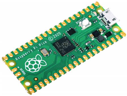
The Raspberry Pi RP2040 is a tiny computer chip. It was designed by the Raspberry Pi Foundation. The Pico board uses this chip and costs about $4. It has 264KB of memory — about 100 times more than an older Arduino Uno board. That extra memory lets you do things like drawing pictures on a small screen.
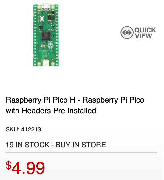 "H" is with headers.
Specs
The Pico is packed with features. Here are the most important ones for beginners:
- Uses the RP2040 chip, designed by the Raspberry Pi Foundation
- Two processor cores running up to 133 MHz — like having two tiny brains
- 264KB of Random-Access Memory (RAM) for running your programs
- 2MB of Flash memory — permanent storage that keeps your programs even when power is off
- 26 General-Purpose Input/Output (GPIO) pins for connecting sensors, LEDs, and motors
- 3 analog inputs that can read voltage levels (for example, from a potentiometer)
- 16 Pulse-Width Modulation (PWM) channels for dimming LEDs or controlling motors
- 2 Serial Peripheral Interface (SPI), 2 Inter-Integrated Circuit (I2C), and 2 Universal Asynchronous Receiver-Transmitter (UART) channels for talking to other devices
- A built-in temperature sensor
- Easy drag-and-drop programming over USB
Key Idea
 A microcontroller is a tiny computer on a single chip. It can read sensors and control motors — all on its own, without needing a big computer nearby!
Runtimes
You can download the latest MicroPython Runtimes for the Raspberry Pi here:
Micropython.org RP2 Runtime Page
USB Cable
The Raspberry Pi Pico uses a USB-Micro connector. You can buy a USB Micro-B to USB-A or USB-C cable on eBay for under $2, or at Microcenter for $5.
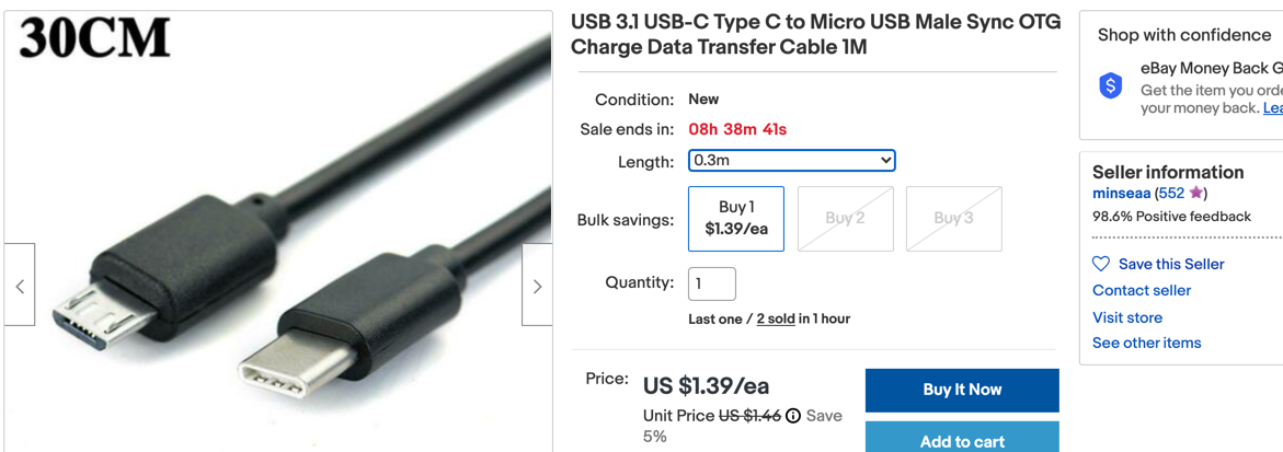 - image from ebay
Monty's Tip
 If your Pico does not connect, try a different USB cable — some cables only carry power and cannot send data.
Pico Pinout
The pinout diagram for the Raspberry Pi Pico is shown below.
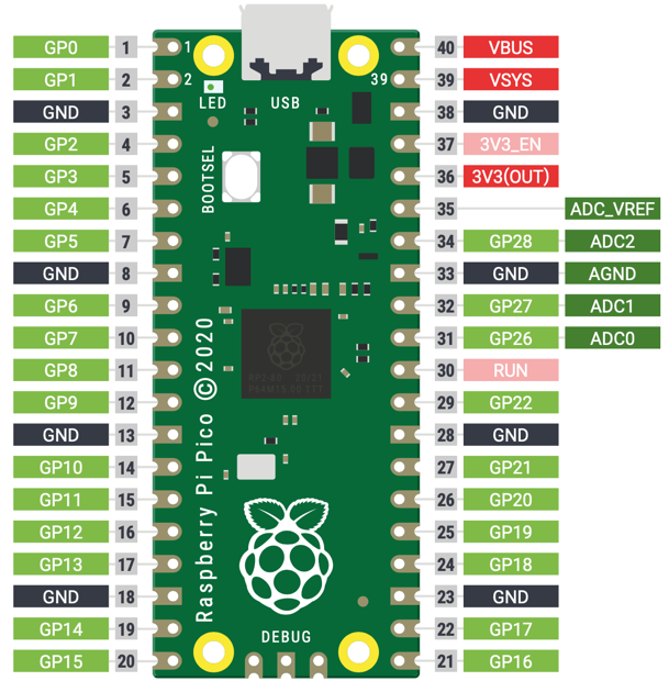
The Pico has 40 pins in total. Here is how they are arranged:
- Pin 1 is in the upper-right corner when the USB connector faces up.
- The numbers go down the left side, then back up the right side.
- Pin 40 is in the upper-right corner.
When you write a program for the Pico, you always use the GP number (for example, GP0 or GP15). You do not use the pin number printed on the board.
The diagram above shows the top view. Pins 1, 2, and 40 are labeled next to each pin.
Pins with a black background (pins 3, 8, 13, 18, 23, 28, 33, and 38) are all ground (GND) pins.
Here is a table explaining the most common pin labels:
| Label | Name | Description |
|---|---|---|
| V3 | 3.3 volts power | Provides 3.3 V power — the same voltage the Pico uses internally. You can use this to power small sensors. |
| VSYS | ~2–5 volts power | Connected directly to the Pico's internal power system. Stays on as long as the Pico has power. |
| VBUS | 5 volts power | Takes 5 V power from the USB port. Useful for hardware that needs more than 3.3 V. |
| GND | 0 volts ground | Completes the circuit for any component you connect. Several GND pins are spread around the board. |
| GPxx | General-Purpose Input/Output pin number xx | The GPIO pins your program can use, labeled GP0 through GP28. |
| GPxx_ADCx | GPIO pin with analog input | A GPIO pin that can also read analog voltages — but not both digital and analog at the same time. |
| ADC_VREF | Analog-to-Digital Converter (ADC) voltage reference | A special input pin that sets the reference voltage for analog inputs. |
| AGND | ADC 0 volts ground | A special ground pin to use alongside ADC_VREF. |
| RUN | Enables or disables your Pico | Used to start or stop the Pico from another microcontroller. |
You Can Do This!
 Reading a pinout diagram can feel overwhelming at first. That is completely normal — just focus on the pins you need for each project, one at a time!
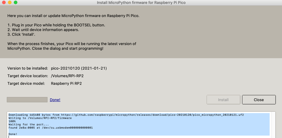
Steps To Get MicroPython Running on the Mac
Follow these steps to load MicroPython onto your Pico:
- Download the MicroPython UF2 file from the MicroPython website.
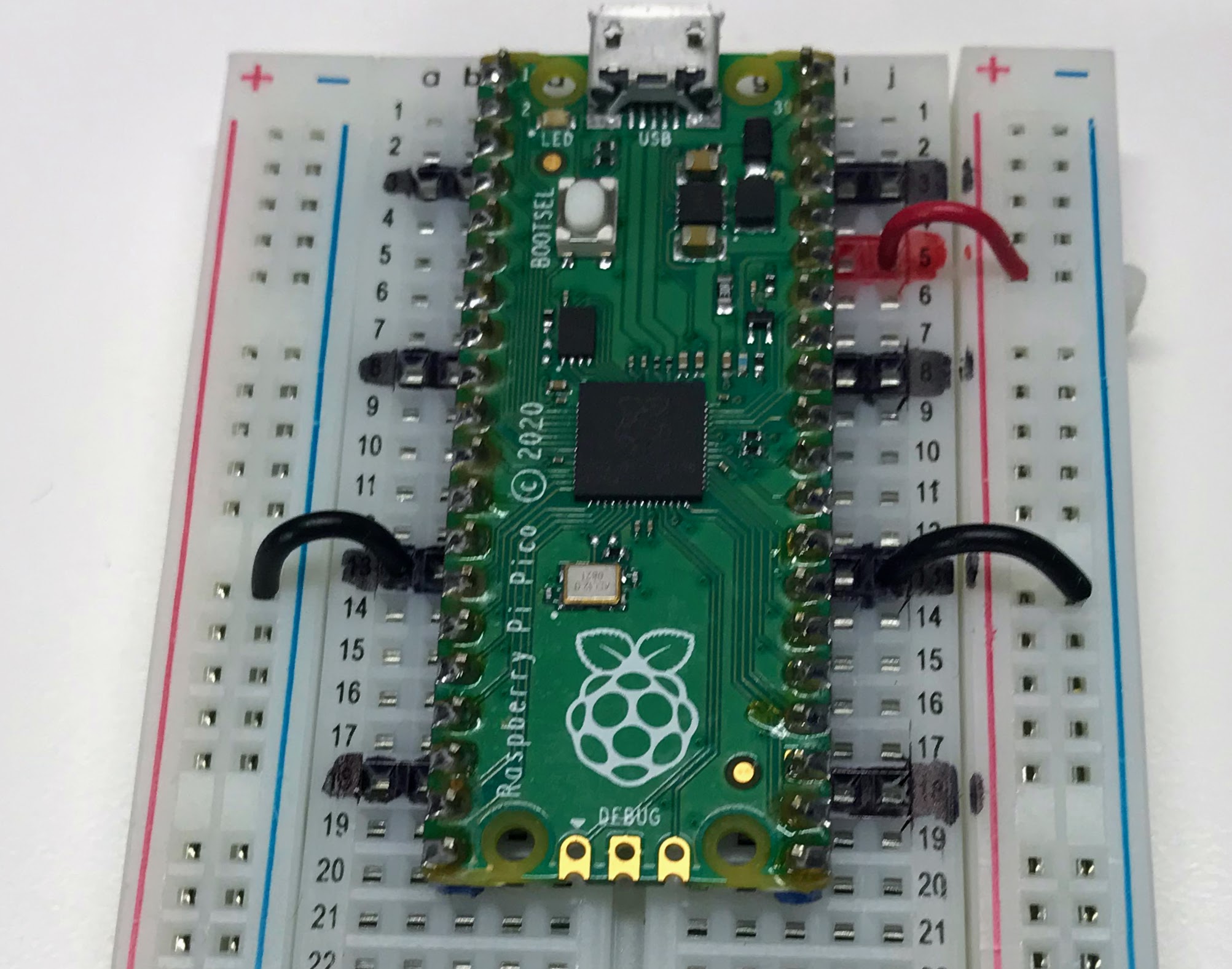
- Hold down the BOOTSEL button on your Pico.
- While holding BOOTSEL, plug the Pico into your computer's USB port.
- Release the BOOTSEL button. Your Pico will appear as a storage drive called RPI-RP2.
- Drag and drop the MicroPython UF2 file onto the RPI-RP2 drive.
- Your Pico will restart automatically. You are now running MicroPython!
Using Thonny
Thonny is a free, easy-to-use program for writing MicroPython code. Follow these steps to set it up:
- Download and install the Thonny application.
- Download the Thonny Pico driver.
- Set Thonny to use the Pico interpreter (the program that runs your code).
- Test the connection by typing
help()in the Thonny shell. - Test your setup by running a blink program.
1 2 3 4 5 6 7 | |
Getting The Bootloader Running from the Thonny Python Shell
You can hold the BOOTSEL button while plugging in the Pico. But there is an easier way. Just type this in the Thonny shell:
1 | |
This sends the Pico into Bootloader Mode. The Pico's storage drive will appear on your computer. You can then drag and drop a new UF2 file onto it. The Pico will restart automatically when the copy is done.
Using the Onboard LED
The Pico has a small LED built right onto the board. Here is how to turn it on:
1 2 3 4 5 | |
What each line does:
from machine import Pin— loads the tool we need to control the Pico's pinsimport utime— loads the time tool for creating delaysled_onboard = machine.Pin(25, machine.Pin.OUT)— creates a pin object for the built-in LED on GP25, set as an outputled_onboard.value(1)— sends power to the LED to turn it on
Here is a blink program that turns the LED on and off forever:
1 2 3 4 5 6 7 8 9 10 | |
What each line does:
from machine import Pin— loads the Pin toolimport utime— loads the time toolled = Pin(16, Pin.OUT)— creates a pin object for GP16, set as an outputled.low()— turns the LED off at the startwhile True:— starts a loop that runs foreverled.toggle()— flips the LED state (on → off or off → on)utime.sleep(1)— pauses for 1 second
Press the Play button in Thonny to run the program.
Adding GND Markers
One of the key disadvantages
References
Getting Started Guide
MicroPython RP2040 Reference
MicroPython RP2040 Quick Reference - this web page has details on how MicroPython was ported to the RP2040 Microcontroller.
Book PDF
Raspberry Pi Book PDF Download from HackSpace Commons Attribution-NonCommercial-ShareAlike 3.0 Unported (CC BY-NC-SA 3.0)
Great Work!
 You now know the key parts of the Raspberry Pi Pico! In the next lab, you will start writing programs to make things light up, move, and sense the world around them.