Breadboards
Welcome to Breadboards
 In this lab, you will learn how breadboards work. They are the building blocks of every circuit you will make! Let's build something amazing!
A breadboard is a plastic board full of tiny holes. You push wires and parts into the holes to build a circuit. No glue, no heat, no tools needed. You can easily add or remove parts at any time.
Breadboards are also called solderless breadboards. Solder is a metal that you melt to attach wires permanently. Because a breadboard uses tiny metal clips instead of solder, you can change your circuit in seconds.
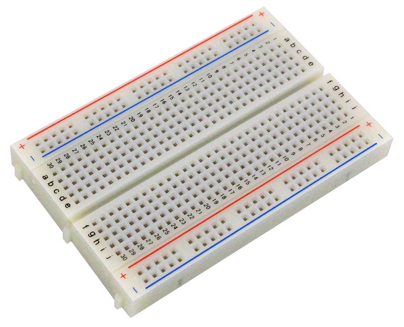
We use standard solderless mini breadboards in our labs. The holes are spaced 1/10th of an inch apart. That is the standard spacing for most electronic parts in the US. Our breadboards are usually half-size boards with 400 holes. They have a center gap and power rails along the left and right edges.
Breadboard Regions and Connections
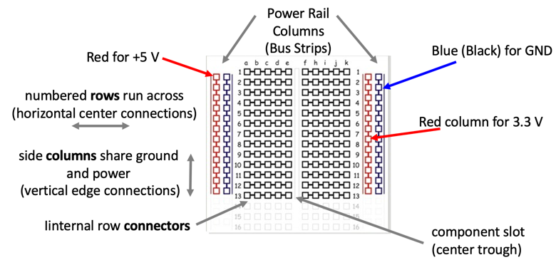
Learning how a breadboard works is the most important skill in this lab. Look at the picture above. You will see two types of regions.
Region 1: Power distribution rails
The long strips along the left and right edges are called power distribution rails. Think of them like extension cords that run along the sides of your circuit. Every hole in the same rail strip is connected inside the breadboard. You use them to share power and ground across your whole circuit.
Key Idea
 Think of a power rail like a power strip. Plug into any hole on that rail and you get the same voltage — just like any outlet in the power strip gives you the same electricity.
The rails are marked with colors:
- The red rail carries power (positive voltage, also called
+orVCC). - The blue rail carries ground (the return path for electricity, also called
-orGND).
Region 2: Row connector region
The middle section is the row connector region. Each numbered row has two groups of holes separated by a gap in the center.
- On the left side of the gap, holes labeled
a,b,c,d, andein the same row are all connected inside the breadboard. - On the right side of the gap, holes labeled
f,g,h,i, andjin the same row are also all connected inside the breadboard. - The gap in the middle is called the center gap or component slot. The two sides of the gap are NOT connected to each other.
Watch Out!
 Never connect a single wire across both sides of the center gap. The gap separates your circuit into two independent sides. Bridging it by accident can cause your circuit to short out.
Parts like buttons and chips have legs on both sides. You place them so their legs straddle the center gap. This way each leg connects to a different side of the row — and the part works correctly.
Pico Placement on Breadboard
For most of our labs, you place the Raspberry Pi Pico so that pin 1 is in row 1 of the breadboard.
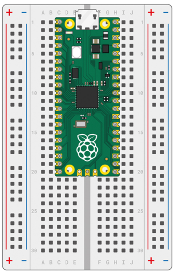
The Pico straddles the center gap. Each pin goes into a different side of the breadboard. This lets you connect wires to every pin without crowding.
When you place the Pico this way, the Ground (GND) pins of the Pico always land in rows 3, 8, 13, and 18 on both sides of the breadboard. You connect one of those ground pins to the blue power rail on the side. That makes the blue rail available as ground for your whole circuit.
You Can Do This!
 Reading pin numbers on the Pico can feel tricky at first. That's completely normal — everyone has to look it up at the start. You've got this, coder!
Pico Placement Annotations
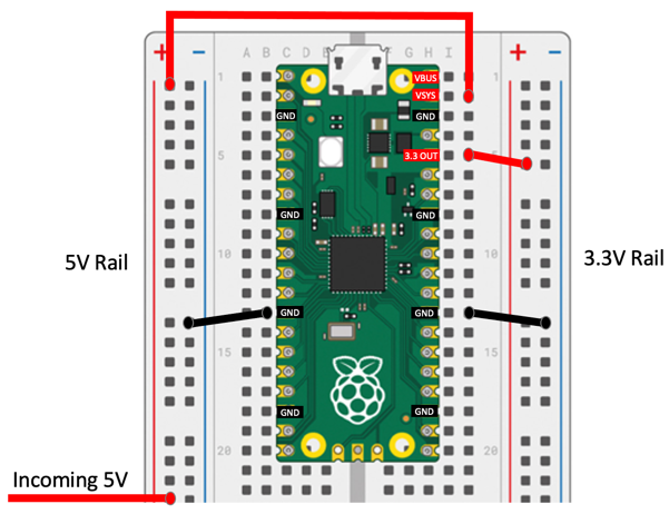
The picture above labels the most important pins on the Pico. Here is what each one means:
- GND — Ground pins. These are the return path for electricity. Connect one to the blue power rail to share ground across your circuit.
- VBUS — This pin carries 5V power from the USB cable. It only has power when the USB cable is plugged in and powered.
- VSYS — This stands for Voltage System Input. When you run the Pico without a USB cable, you connect a battery or power supply here. It accepts any voltage from 1.8V to 5.5V. A built-in circuit converts that voltage to the 3.3V the Pico needs to run.
There is also a pin called 3V3_EN (3.3 Volt Enable). When this pin is connected to ground (LOW), it turns off the 3.3V power inside the Pico. This shuts down the whole board. You usually leave this pin alone unless you specifically need to turn the Pico off from software or another circuit.
Breadboard Connections
Now you know how a breadboard works. Let's look at the basic rules for connecting things:
- Push jumper wires firmly into the holes until they click or feel snug.
- Use the same row to connect two parts together.
- Use the power rails to share voltage and ground across many parts.
- Always connect the blue rail to GND and the red rail to power before wiring your circuit.
- Double-check each connection before you plug in power.
Great Work!
 You now understand how breadboards work! In the next lab, you will use a breadboard and the Pico to build your very first circuit — an LED that blinks.