Raspberry Pi Pico MicroPython Base Robot
Welcome to the Base Bot Lab
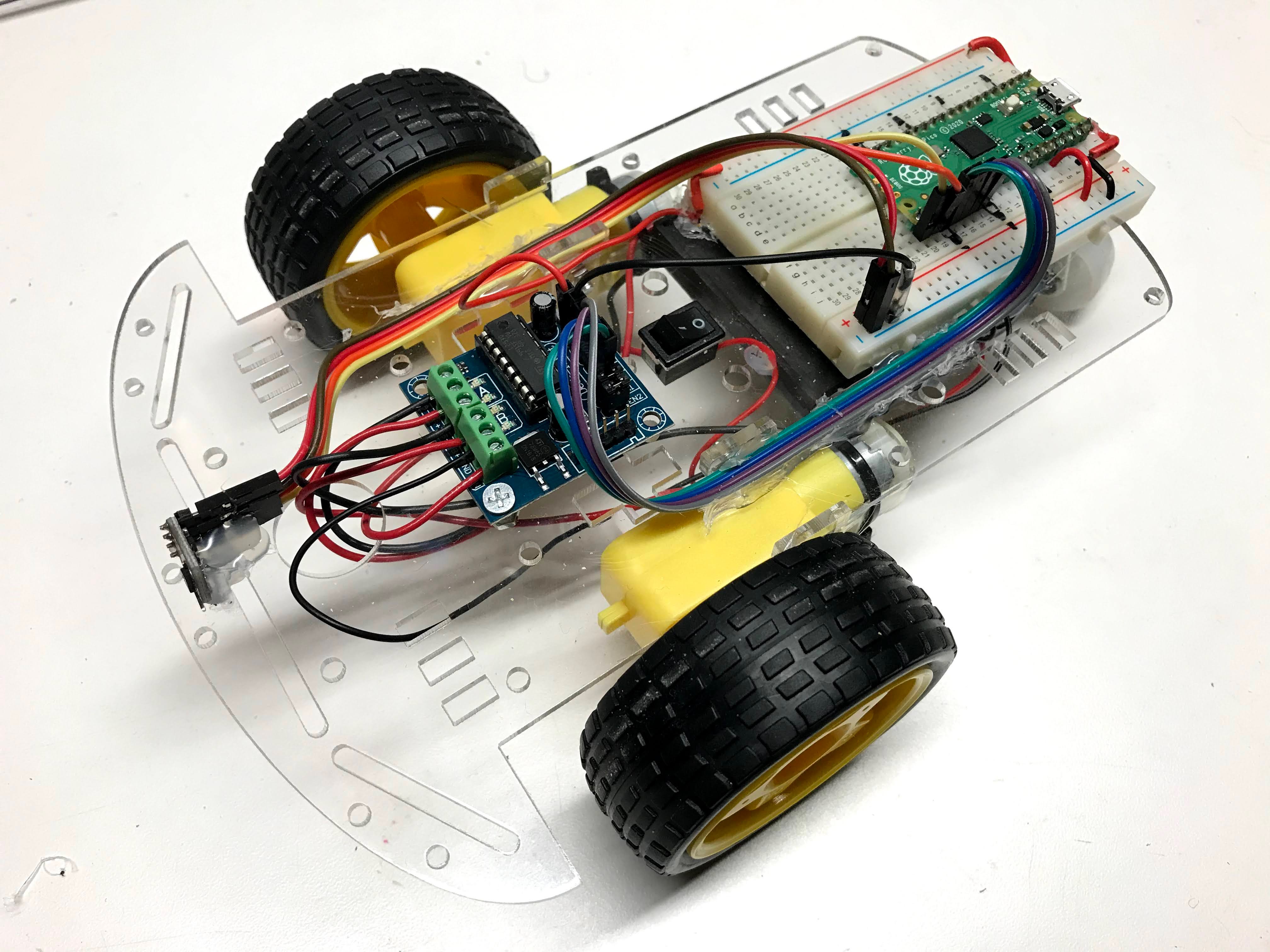
 This is your first robot! You will wire up the parts, write a program, and watch your robot drive around on its own. Let's build it together!
In this lab you will build the base robot. All the other robot projects in this section build on top of what you make here. The robot is programmed entirely in Python, so it fits right in with the Python skills you are learning.
Base Robot Design
Our goal is a robot platform for learning computational thinking. Computational thinking means breaking a big problem into small steps that a computer can follow. Here are the main design goals:
- Low cost (under $25) so that most students can build their own robot.
- Open platform so you can upgrade and swap parts easily.
- Interchangeable parts that work with many different robots.
- Very little soldering needed.
Video
Here is a video of the collision avoidance robot in action:
You can see the forward speed and the turning distance in the video. The robot bumped a wall once — that happens when the turning threshold is set too high. You will learn how to fix that.
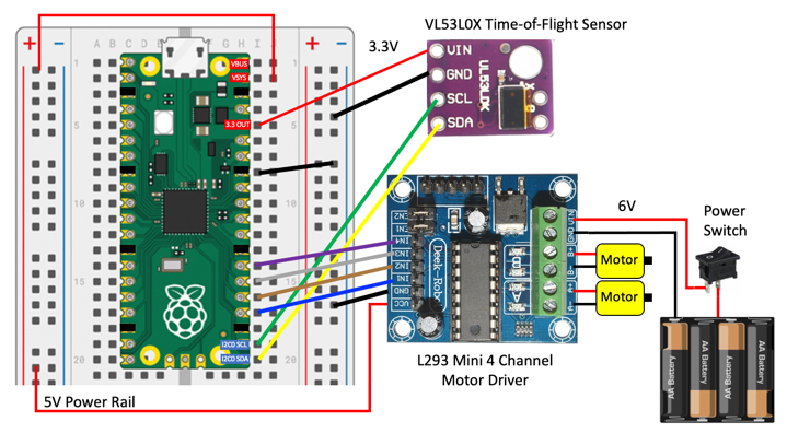
Connection Diagram
Here is the connection diagram for the base robot. Use this diagram when you wire up your parts.
Power Regulation
The robot gets power from a battery pack at 6 volts. That power goes into the motor controller board. The motor controller has a voltage regulator inside it. A voltage regulator is a chip that turns one voltage into a lower, steady voltage. The motor controller turns 6–12 volts into a steady 5 volts. That 5 volts powers the Pico through the VSYS pin. The Pico has its own voltage regulator that brings the 5 volts down to 3.3 volts. The 3.3 volt output (the 3V3 OUT pin) powers the distance sensor.
Watch the Battery Level
 When batteries get low, the voltage drops below 5 volts. Then the 3.3 volt output becomes unstable and the sensor gives bad readings. Replace your batteries if the robot starts behaving strangely.
Hardware Description
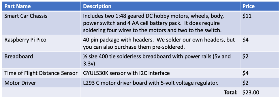
Here is a summary of the main parts and their prices as of June 2021. Some parts ship from overseas and may take 2–3 weeks to arrive.
Here is a Google Sheet with all the parts:
Detailed Parts List Google Sheet
Two Wheel Drive Smart Car Chassis
All robots in this course use a standard two-wheel drive (2WD) SmartCar Chassis. 2WD means two powered wheels and one free-rolling caster wheel. You can find these online from many sellers.
- $5 Cytron 2WD Smart Car Chassis
- YouTube Video of Assembly — Note: the video does not remove the backing paper from the plastic and mounts the battery on top. We prefer the battery on the bottom.
Motor Driver
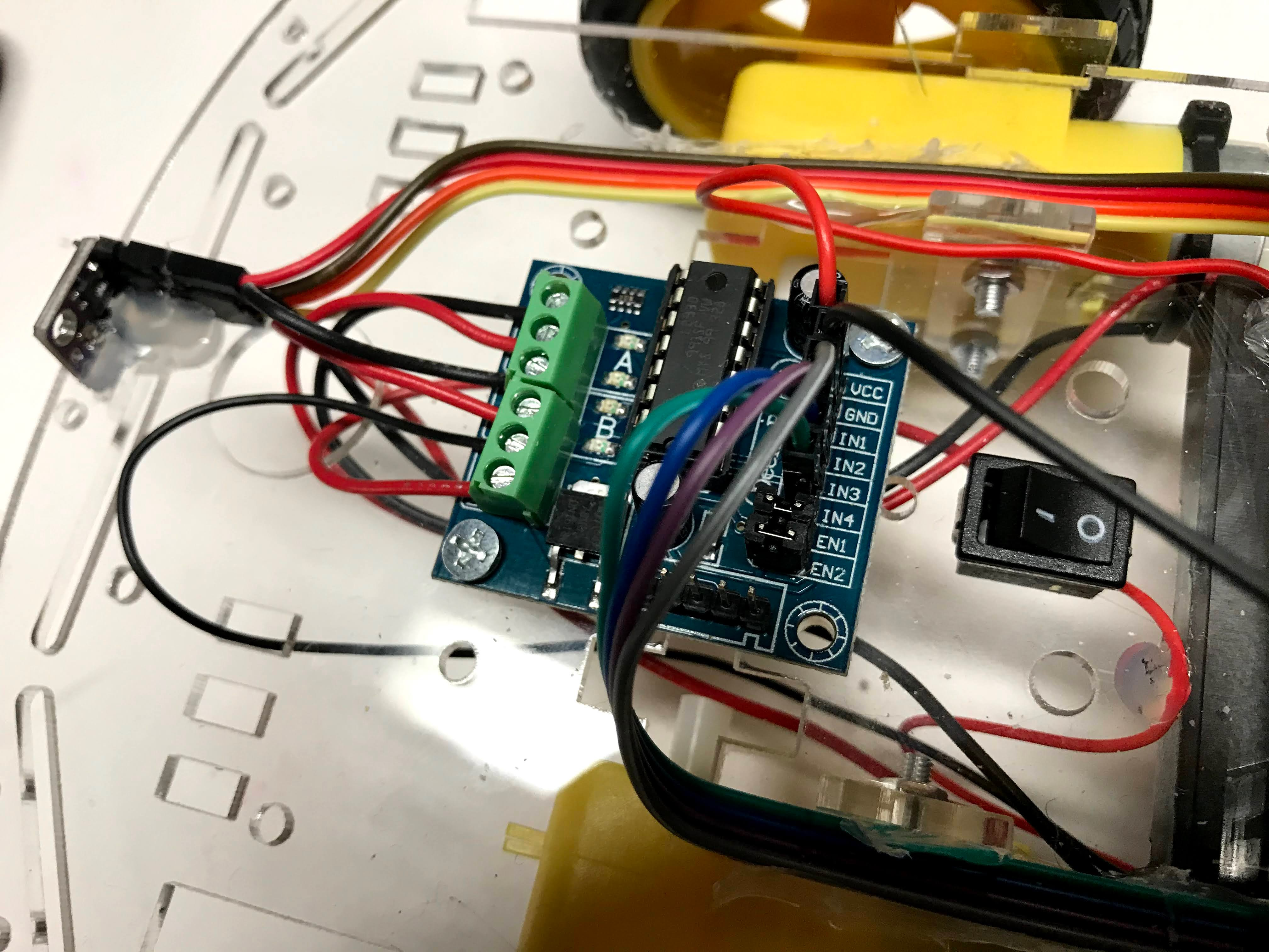
The motor driver is a board that takes small signals from the Pico and uses them to control the motors. The motors need more power than the Pico can deliver directly, so the motor driver acts as a power amplifier.
Software
All software for this robot is written in MicroPython.
Time-of-Flight Distance Sensor
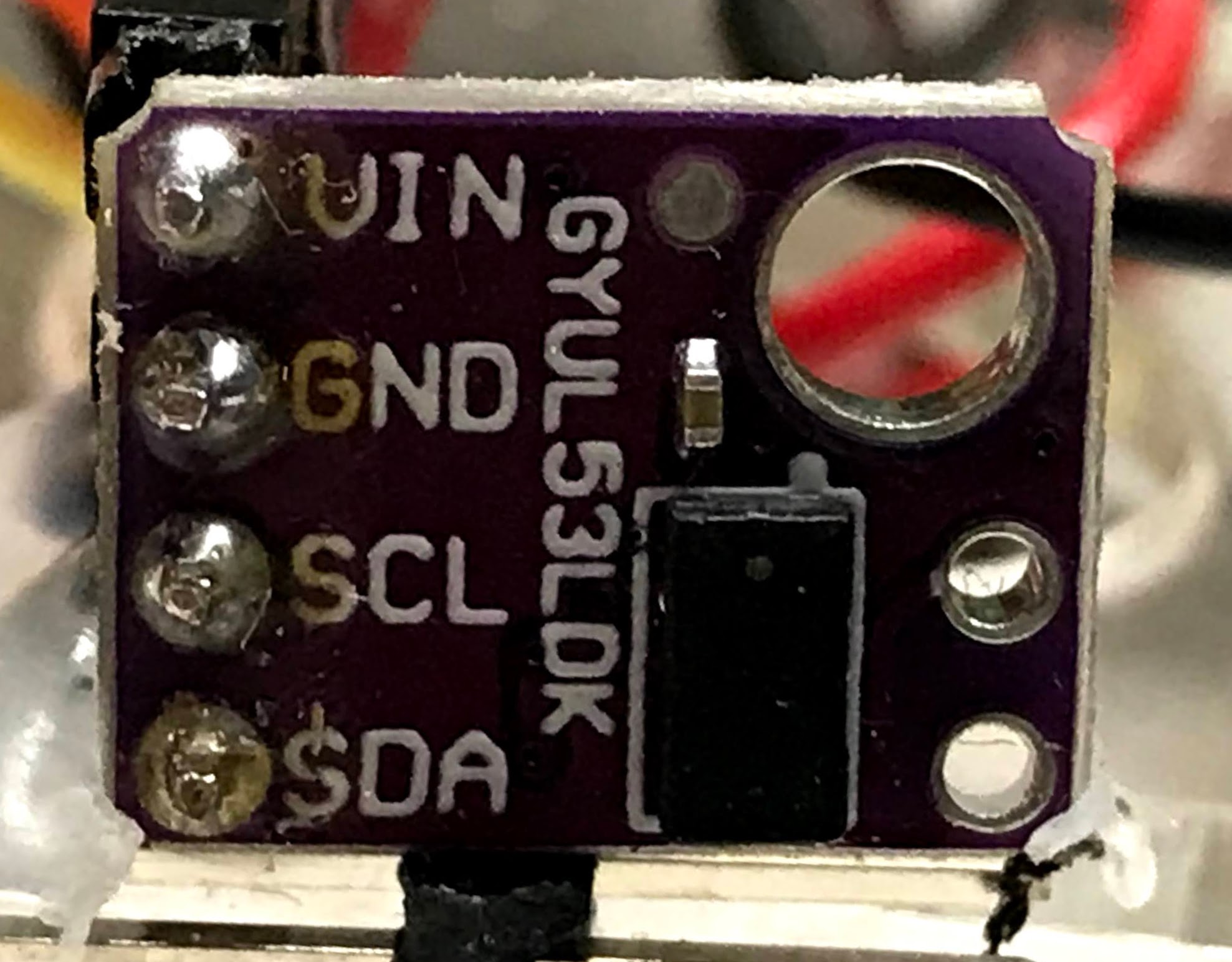
This robot uses the VL53L0X time-of-flight distance sensor. A time-of-flight sensor works by shooting a tiny laser pulse at an object and measuring how long it takes for the light to come back. This is very accurate and reliable. The sensor talks to the Pico using the I2C (Inter-Integrated Circuit) bus. I2C is a way to connect multiple devices to the Pico using just two wires — one for data and one for a clock signal.
After you wire up power (VCC to the 3.3 volt rail and GND to ground), connect the I2C data and clock pins:
1 2 3 | |
What each line does
sda = machine.Pin(16)— names pin 16 as the data line (SDA stands for Serial Data)scl = machine.Pin(17)— names pin 17 as the clock line (SCL stands for Serial Clock)i2c = machine.I2C(0, sda=sda, scl=scl)— creates the I2C connection using those two pins
Older robots in this course used ultrasonic ping sensors. Ping sensors become unreliable when batteries run low, so we switched to the time-of-flight sensor.
Testing the Sensor Connections with the I2C Scanner
Run this short program to check that the sensor is wired correctly:
1 2 3 4 5 6 7 | |
What each line does
import machine— loads the MicroPython library for hardware controli2c.scan()— checks the I2C bus and returns a list of device addressesprint(...)— shows the result in the console
You should see a number printed in the console. The VL53L0X sensor normally shows up at address 41 (decimal), which is the same as 0x29 (hexadecimal).
Download the VL53L0X Driver
The VL53L0X sensor needs a driver file saved on the Pico. A driver is a piece of code that knows how to talk to a specific piece of hardware.
Download the driver here: VL53L0X.py
Save that file as VL53L0X.py on your Pico using Thonny.
Time-of-Flight Sensor Test
Once the driver file is saved on the Pico, run this test:
1 2 3 4 5 6 7 8 9 10 11 12 13 14 15 | |
What each line does
tof = VL53L0X.VL53L0X(i2c)— creates a sensor object so your code can talk to the sensortof.start()— wakes up the sensor and tells it to start taking measurementstof.read()— returns the distance to the nearest object in millimeterstime.sleep(0.1)— pauses for 0.1 seconds between readings
Numbers will appear in the console. About 30 means an object is very close. About 1300 means the object is about 1.3 meters away.
Motor Drive Test
After you connect the four motor wires to the motor driver, run this test to check that each wheel spins in the right direction:
1 2 3 4 5 6 7 8 9 10 11 12 13 14 15 16 17 18 19 20 21 22 23 24 25 26 27 28 29 30 31 32 33 34 35 | |
What each line does
PWM(Pin(21))— sets up Pulse Width Modulation on pin 21 (PWM lets you control speed)duty_u16(POWER_LEVEL)— sets the motor power from 0 (off) to 65025 (full)duty_u16(0)— stops the motor by setting power to zero
Right vs. Left — It's Confusing!
 "Right" and "Left" mean the robot's right and left — as if you were sitting inside it facing forward. If the robot is facing you, its "right" wheel is on your left side. Think of it like driving a car.
Watch which wheels spin and in which direction. If a wheel spins backwards when you expect it to go forward, swap the wires for that wheel on the motor driver.
Sample Drive and Turn Functions
Your robot needs five basic movements:
- Forward — both wheels spin forward
- Reverse — both wheels spin backward
- Turn Right — right wheel goes backward, left wheel goes forward
- Turn Left — left wheel goes backward, right wheel goes forward
- Stop — all motors off
For each movement, you must set all four PWM signals. Never run a motor forward and backward at the same time.
1 2 3 4 5 6 7 8 9 10 11 12 13 14 15 16 17 18 19 20 21 22 23 24 25 26 27 28 29 30 31 32 33 34 35 | |
Turning Logic
This is the main decision loop. It reads the sensor and decides what to do:
1 2 3 4 5 6 7 8 9 10 | |
Stop All Motors Program
PWM signals keep running on the Pico even after your main program stops. This is because the Pico uses a separate built-in processor to generate those signals. Save this as a separate file called stop-all-motors.py and keep it open in Thonny so you can run it quickly:
1 2 3 4 5 6 7 8 9 10 11 12 13 14 15 16 17 18 19 | |
What each line does
- Each
PWM(Pin(...))line reconnects to the motor control pin. - Each
duty_u16(0)line cuts the power to that motor.
Collision Avoidance Logic
The full program combines the sensor and the motor functions. The robot reads the distance, and if something is too close it backs up and turns. Otherwise it drives forward.
Final Program
To run the robot on battery power without a computer, save the program as main.py on the Pico. The Pico runs main.py automatically when it powers up.
Note
Make sure you have the VL53L0X distance sensor driver saved on the Pico before running this program.
1 2 3 4 5 6 7 8 9 10 11 12 13 14 15 16 17 18 19 20 21 22 23 24 25 26 27 28 29 30 31 32 33 34 35 36 37 38 39 40 41 42 43 44 45 46 47 48 49 50 51 52 53 54 55 56 57 58 59 60 61 62 63 64 65 66 67 68 69 70 71 72 73 74 75 76 77 78 79 80 81 82 83 84 85 86 87 88 89 90 91 92 93 94 95 96 97 98 99 | |
More to Explore
- Change the
POWER_LEVELvalue. What is the lowest value that still makes the robot move? - Change the
TURN_THRESHOLD. What happens if you make it very small? What about very large? - Can you make the robot randomly turn left or right? Use
import randomandrandom.randint(0, 1). - What other parameters would you like to be able to adjust? Think about how you would add them.
Great Work!
 You built and programmed your first robot! It can now drive around and avoid obstacles all by itself. Next, you will add LEDs and sensors to make it even smarter.