OLED Setup
Let's Get Your Display Ready
 Every MicroPython program needs a setup section at the top. This page shows you the setup code for both I2C and SPI OLED displays. Pick the one that matches your display!
At the top of every MicroPython program, you write a few lines of setup code. This setup code tells the program which libraries to load, which pins to use, and which devices to create. You do this once before your main code runs.
We will look at the I2C setup first. Then we will look at the SPI setup.
I2C Scanner
Your microcontroller can have many Inter-Integrated Circuit (I2C) devices connected at the same time. Each device needs a unique address so the microcontroller knows which one to talk to. Most OLED displays come set to address 60 by default. The hexadecimal version of that address is 3C.
Run this code to check that your display is connected and find its address:
1 2 3 4 5 6 7 | |
What each line does:
import machine— loads the hardware library.sda = machine.Pin(0)— names the data wire pin.scl = machine.Pin(1)— names the clock wire pin.i2c = machine.I2C(0, ...)— creates the I2C connection at 400,000 signals per second.print(...)— shows the list of device addresses found on the bus.
Expected output: [60]
Key Idea
 I2C is like a telephone party line. Every device shares the same two wires, but each device has its own address number so the microcontroller can call the right one.
SSD1306 Examples
SSD1306 I2C Setup
Once the scanner finds your display, you can load the SSD1306 driver and show text.
1 2 3 4 5 | |
What each line does:
from ssd1306 import SSD1306_I2C— loads just the I2C class from the ssd1306 driver file.oled = SSD1306_I2C(128, 64, i2c)— creates the display object. The numbers 128 and 64 are the screen width and height in pixels.oled.text('Hello World!', 0, 0, 1)— places text at x=0, y=0. The1means white pixels.oled.show()— sends everything you have drawn to the physical screen. Nothing appears until you call this!
Watch Out!
 You must call
 oled.show() at the end. Without it, nothing appears on the screen. Think of it like pressing "send" after writing a text message.
SSD1306 SPI Setup
Serial Peripheral Interface (SPI) is faster than I2C but needs more wires.
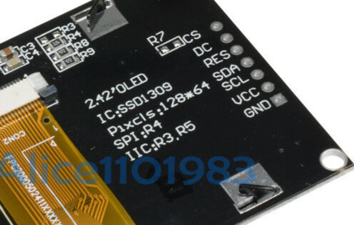
Back connections:
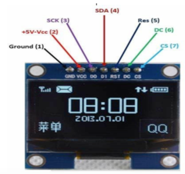
Front labels on OLED with SPI:
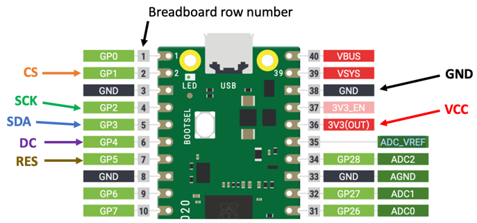
Here is the connection diagram:
Here is the code:
1 2 3 4 5 6 7 8 9 10 11 12 13 14 | |
What each line does:
import machine— loads the hardware library.import ssd1306— loads the display driver.spi_sck = machine.Pin(2)— names the SPI clock pin.spi_tx = machine.Pin(3)— names the SPI data pin (also called MOSI).spi = machine.SPI(...)— creates the SPI bus at 100,000 signals per second.CS = machine.Pin(1)— the Chip Select pin. Pull it low to talk to the display.DC = machine.Pin(4)— the Data/Command pin. Tells the display if you are sending a drawing command or pixel data.RES = machine.Pin(5)— the Reset pin. Restarts the display chip.oled = ssd1306.SSD1306_SPI(...)— creates the display object using all five pins.oled.text(...)— draws text.oled.show()— sends the drawing to the screen.
SH1106 I2C Setup
If your display uses the SH1106 chip instead of the SSD1306, use this setup:
1 2 3 4 5 6 7 8 9 10 | |
What each line does:
from machine import Pin, I2C— loads Pin and I2C classes from the machine library.import sh1106— loads the SH1106 display driver.- Lines 3–4 — set up the data and clock wires (same as SSD1306).
i2c = I2C(0, ...)— creates the I2C bus.oled = sh1106.SH1106_I2C(128, 64, i2c)— creates the display object.oled.text(...)— draws text.oled.show()— sends the drawing to the screen.
References
MicroPython SSD1306 Driver on GitHub
Great Work!
 You now know how to set up both I2C and SPI OLED displays. Next, you will try full working examples for each type!