OLED SSD1306 Examples
Welcome to the SSD1306 Lab
 In this lab, you will use the SSD1306 — the most popular OLED display chip. You will show text, count to 50, and animate a moving box. Let's get started!
Using the SSD1306 with I2C Interfaces
Add the ssd1306 Python Module
You need to add the SSD1306 driver to your Pico before you can use it. You can do this in Thonny using the Tools → Manage Packages... menu. Search for ssd1306 and install it. You need to do this once for each new device type you use.
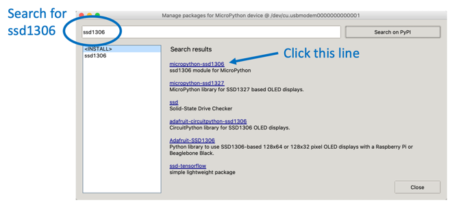
If the Manage Packages menu is grayed out, go to the Shell at the bottom of Thonny and type the install command there.
I2C Hello World
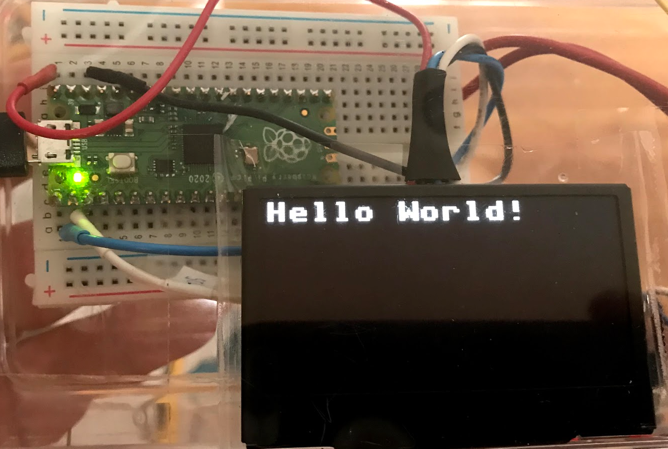
This is the first program you should try. It shows "Hello World!" on your display.
1 2 3 4 5 6 7 8 9 10 11 12 | |
What each line does:
import machine— loads the hardware library.from ssd1306 import SSD1306_I2C— loads only the I2C class from the ssd1306 driver.sda = machine.Pin(0)— names the data wire pin.scl = machine.Pin(1)— names the clock wire pin.i2c = machine.I2C(0, ...)— creates the Inter-Integrated Circuit (I2C) bus. Thefreq=400000sets the speed to 400,000 signals per second.oled = SSD1306_I2C(128, 64, i2c)— creates the display object.128is the width.64is the height.oled.fill(0)— fills the screen with black (0 means off).oled.text("Hello World!", 0, 0)— draws text starting at column 0, row 0 (top-left corner).oled.show()— sends everything to the screen. Nothing appears until you call this!print('Done')— shows a message in the console.
After this program runs you should see the text on your OLED display.
Monty's Tip

oled.show() is like pressing the "send" button. You can draw as many things as you want, but nothing appears on screen until you call show(). Always put it last!
SH1106 Example
If your display uses the SH1106 chip instead of the SSD1306, use this setup. The SH1106 chip has slightly more internal memory (132 x 64 pixels vs. 128 x 64 pixels), but the programming is very similar.
1 2 3 4 5 6 7 8 9 10 11 12 13 14 15 | |
What each line does:
1–2. Import lines — load the hardware library and SH1106 driver.
3–4. Pin setup — same data and clock pins as SSD1306.
5. i2c = I2C(0, ...) — creates the I2C bus.
6. display = sh1106.SH1106_I2C(128, 64, i2c, Pin(4), 0x3c) — creates the display. 0x3c is the display address in hexadecimal.
7. display.sleep(False) — wakes the display. Some SH1106 displays start in sleep mode.
8–10. Drawing and showing — same as SSD1306.
Counter Example
In this example, you will update the display 50 times. A counter counts from 1 to 50. There is a short pause between each update so you can watch it count.
1 2 3 4 5 6 7 8 9 10 11 12 13 14 15 16 17 | |
What each line does:
1–6. Setup — loads libraries and creates the display.
7. for i in range(1, 51): — loops 50 times. Each time, i is one number higher.
8. oled.fill(0) — clears the screen before drawing the next frame.
9. oled.text('CoderDojo Rocks!', 0, 0, 1) — draws the title every frame so it stays visible.
10. oled.text(str(i), 40, 20, 1) — converts the number i to text with str(), then draws it at x=40, y=20.
11. oled.show() — sends the new frame to the screen.
12. utime.sleep(0.1) — waits 0.1 seconds (100 milliseconds) so you can see each number.
Animated Box
This example draws a title and a border rectangle. Then it draws a small filled box that slides from left to right across the display.
1 2 3 4 5 6 7 8 9 10 11 12 13 14 15 16 17 18 19 20 21 22 23 24 25 26 27 28 29 30 31 | |
What each line does:
1–7. Setup — loads libraries and creates the I2C bus and display.
8. display.fill(0) — clears the screen.
9. display.text(...) — draws the title.
10. display.hline(0, 9, 127, 1) — draws a horizontal line. Arguments: x start, y position, length, color.
11. display.vline(0, 10, 32, 1) — draws a vertical line. Arguments: x position, y start, height, color.
12. for i in range(0, 118): — loops 118 times, one position for each step.
13. display.fill_rect(i, 10, 10, 10, 1) — draws the moving box. Arguments: x, y, width, height, color.
14. display.fill_rect(10, 21, 30, 8, 0) — draws a black rectangle to erase the previous number.
15. display.text(str(i), 10, 21, 1) — draws the current position as a number.
16. display.show() — sends the new frame to the screen.
Key Idea
 To erase something on an OLED, you draw a black rectangle over it. Black pixels are "off" — they produce no light. Drawing in black is the same as erasing!
Install SSD1306 Module
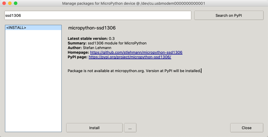
ssd1306 module
SSD1306 Library — click the RAW button, then right-click and choose "Save As" to download the file.
SSD1306 vs. SH1106
There is only one small difference between SSD1306 and SH1106. The SH1106 chip has an internal memory of 132 x 64 pixels. The SSD1306 only has 128 x 64 pixels. For most programs, you will not notice any difference.
The SPI interface
The four-wire I2C connection is great for beginners who do not want to hook up many wires. But sometimes you need a faster screen. This is when the Serial Peripheral Interface (SPI) connection is useful.
SPI Baudrate
The baud rate is the number of signals the SPI bus sends per second. You can read more about Pico SPI baud rates here: https://raspberrypi.github.io/pico-sdk-doxygen/group__hardware__spi.html#ga37f4c04ce4165ac8c129226336a0b66c
The seven wires on the back of the SPI OLED screens are the following, reading from top to bottom when looking at the back of the display:
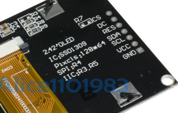
- CS — Chip Select — pin 4
- DC — Data/Command — pin 5
- RES — Reset — pin 6
- SDA — Data — SPI0 TX GP7 pin 10
- SCL — Clock — Connect to SPI0 SCK GP6 pin 9
- VCC — Connect to the 3.3V Out pin 36
- GND — pin 38 or any other GND pin
Pico Pins
1 2 3 4 5 6 7 8 9 10 | |
SCK is the clock — connect this to the OLED SCL pin. MOSI is the data line that sends data from your Pico to the display. Connect this to the SDA pin.
From the SDK: https://datasheets.raspberrypi.org/pico/raspberry-pi-pico-python-sdk.pdf Section 3.7
- SPI0_SCK — pin 6
- SPI0_MOSI — pin 7
- SPI0_MISO — pin 8
This contradicts p122 in GET STARTED WITH MICROPYTHON ON RASPBERRY PI PICO
1 2 3 | |
SPI Terms
Master Out Slave In (MOSI) is the wire that carries data from the Pico to the display.
We send the data to the SPI RX (Receive) port on the Pico. These are pin 1 (GP0) or pin 6 (GP4).
Sample Nonworking SPI Code
From the documentation:
From
spi is an SPI object, which has to be created beforehand and tells the ports for SCLJ and MOSI. MISO is not used.
dc is the GPIO Pin object for the Data/Command selection. It will be initialized by the driver.
res is the GPIO Pin object for the reset connection. It will be initialized by the driver. If it is not needed, it can be set to None or omitted. In this case the default value of None applies.
cs is the GPIO Pin object for the CS connection. It will be initialized by the driver. If it is not needed, it can be set to None or omitted. In this case the default value of None applies.
1 2 3 4 5 6 7 8 9 10 11 12 13 14 15 16 17 18 19 20 21 22 23 24 25 26 27 28 29 30 31 | |
References
DIY More OLED Product Description
Great Work!
 You have run Hello World, counted to 50, and animated a sliding box. You are making your display come alive. Next, try changing the text or the animation speed to make it your own!