Display Wiring Harness
Welcome to the Wiring Harness Lab
 In this lab, you will build a wiring harness — a neat bundle of wires that makes it easy to connect your display every time. No more loose wires falling off your breadboard!
Simple sensors only need two or three wires. Displays need up to seven wires. When you use a breadboard, it is easy to accidentally pull one wire out. A loose wire means your display stops working.
To keep your display running reliably, you can make a wiring harness. A harness bundles all seven wires together with a little hot glue. Once you build it, connecting your display takes just one move.
What You Need
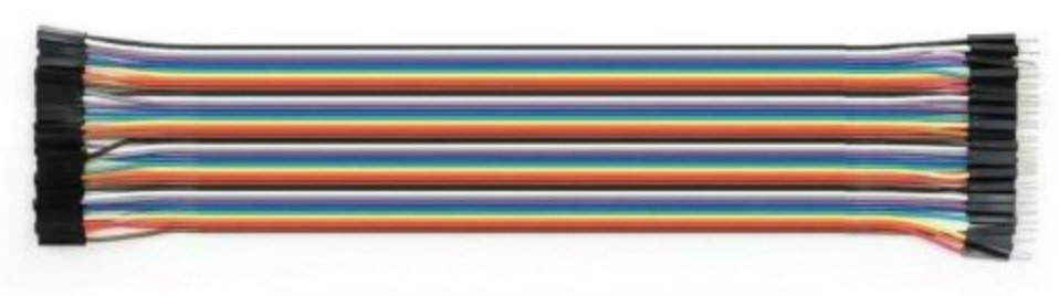
Start by buying some 20 cm long Male-Female Dupont ribbon connectors from eBay. The price is about $8 for 120 connectors. Make sure to get the Male-Female version. Male-Female means one end has a pin (male) and the other end has a socket (female).
Building the Harness
Follow these steps to build your harness.
Step 1 — Separate seven wires
- Pull seven wires out of the ribbon cable.
- Keep the wires connected at one end to form a flat bundle.
- Make sure the black wire is on one edge of the bundle and the red wire is on the other edge.
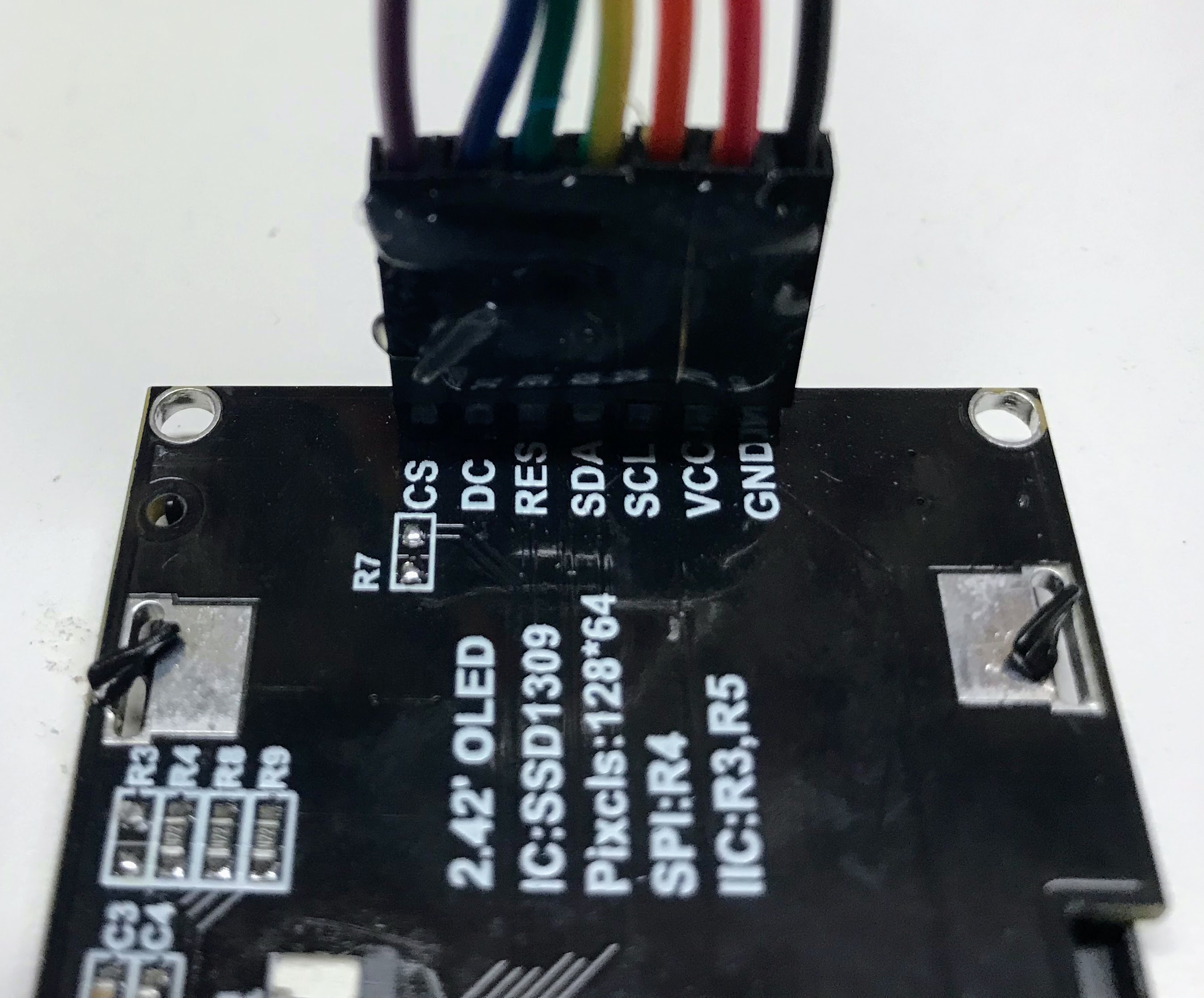
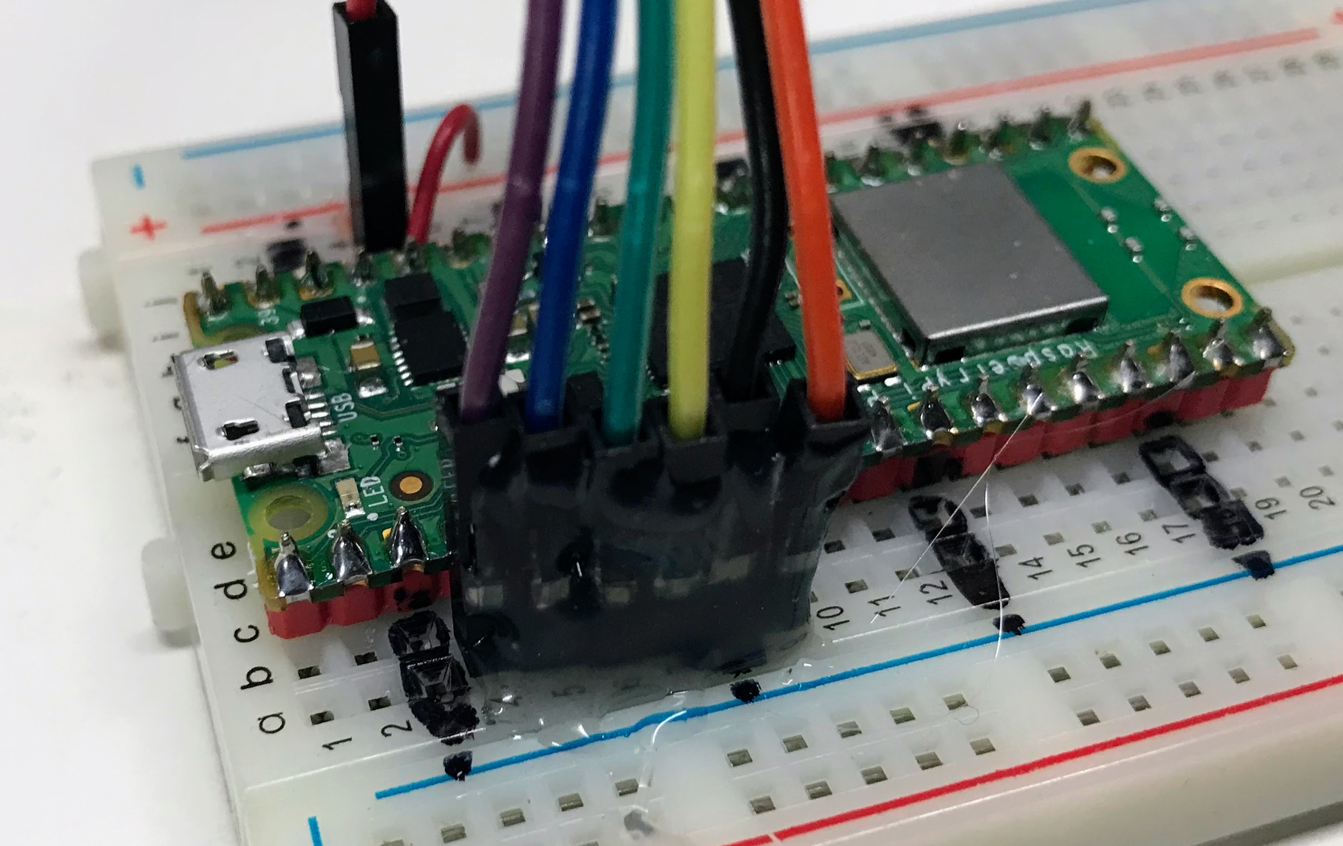
You can see a close-up of each color and its connection in the picture below.
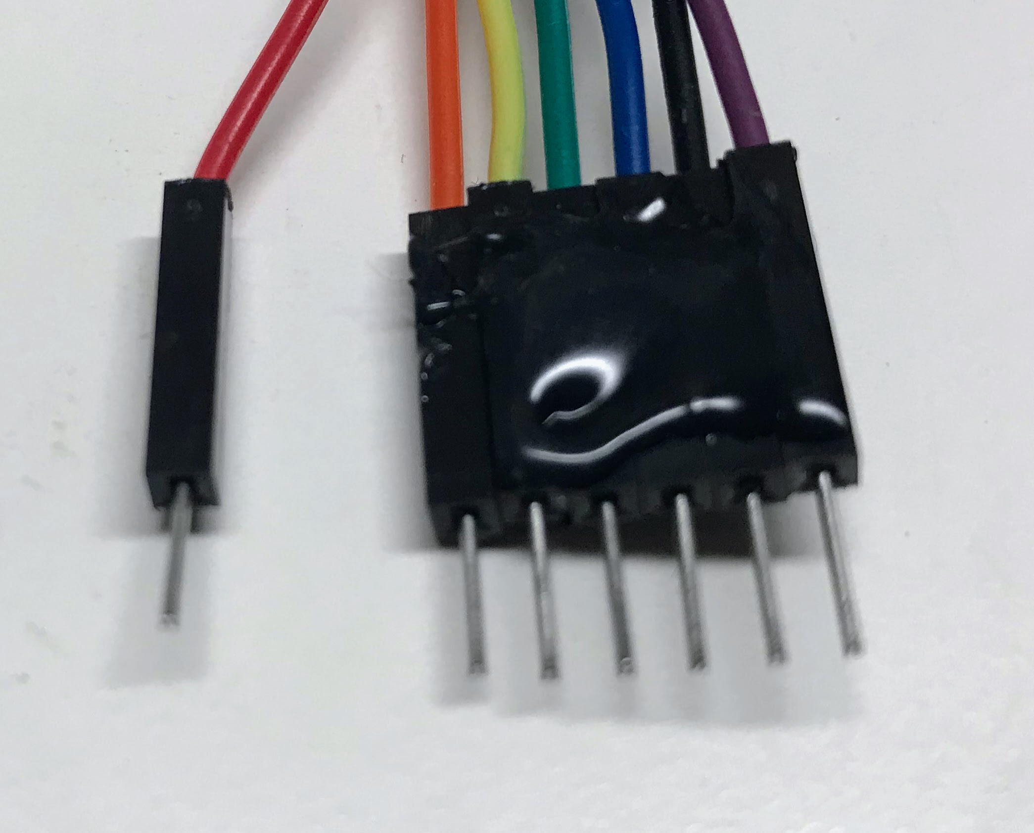
Step 2 — Rearrange the wires at the Pico end
At the Pico end of the cable, you need to make two changes:
- Separate the red wire from the rest of the group. Connect the red wire to the 3.3V regulated output pin on your Raspberry Pi Pico.
- Move the black Ground (GND) wire so it sits between the blue Chip Select (CS) and purple Data/Command (DC) wires. This lets all remaining wires plug in as one solid block.
Watch Out!
 You must make sure the black wire connects to GND. It is easy to accidentally plug the cable in backwards. Always check the cable orientation before you power on your board.
Step 3 — Plug the harness into your breadboard
- Plug the block of wires into your breadboard from rows 3 to 9.
- The red VCC wire connects to 3.3V on the Pico separately.
- The black GND wire sits at row 8 in the middle of the block.
We designed these connections with these two rules:
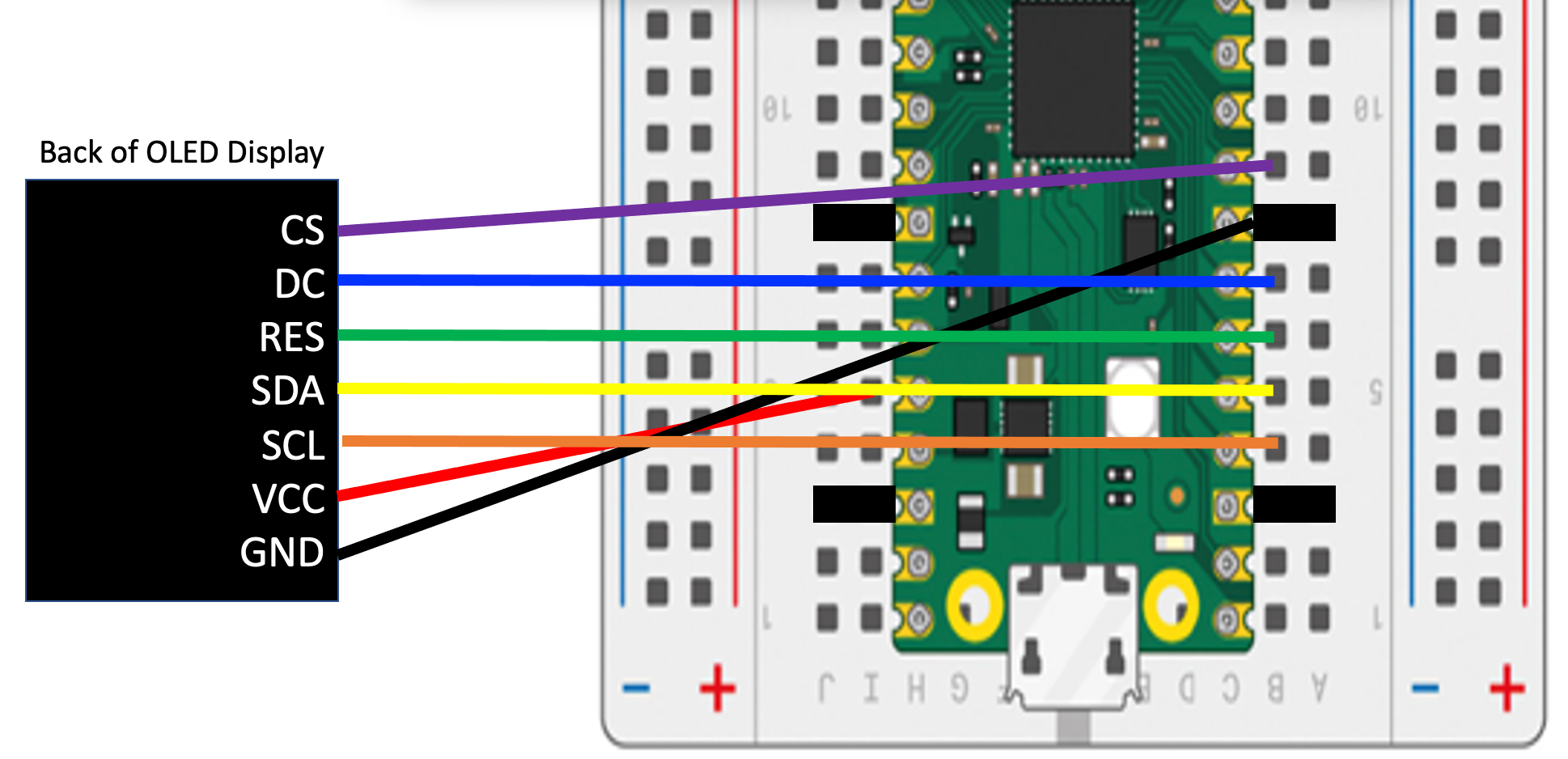
- The Clock (SCL) and Data (SDA) wires must connect to breadboard rows 4 and 5. This is where SPI0 CLK and SPI0 TX pins are located on the standard Pico layout.
- The other three signal wires — Reset (RES), Data/Command (DC), and Chip Select (CS) — can connect to any pins. We use rows 6, 7, and 9 so the cable plugs in as one straight block. GND sits at row 8.
Once you add hot glue to keep the pins in order, the harness is very reliable. Connecting your display becomes fast and easy every time.
Monty's Tip
 A small dot of hot glue at each end of the wire bundle keeps the pins in the right order. Let the glue cool fully before you plug in the harness. Your future self will thank you!
Cable Wiring Diagram
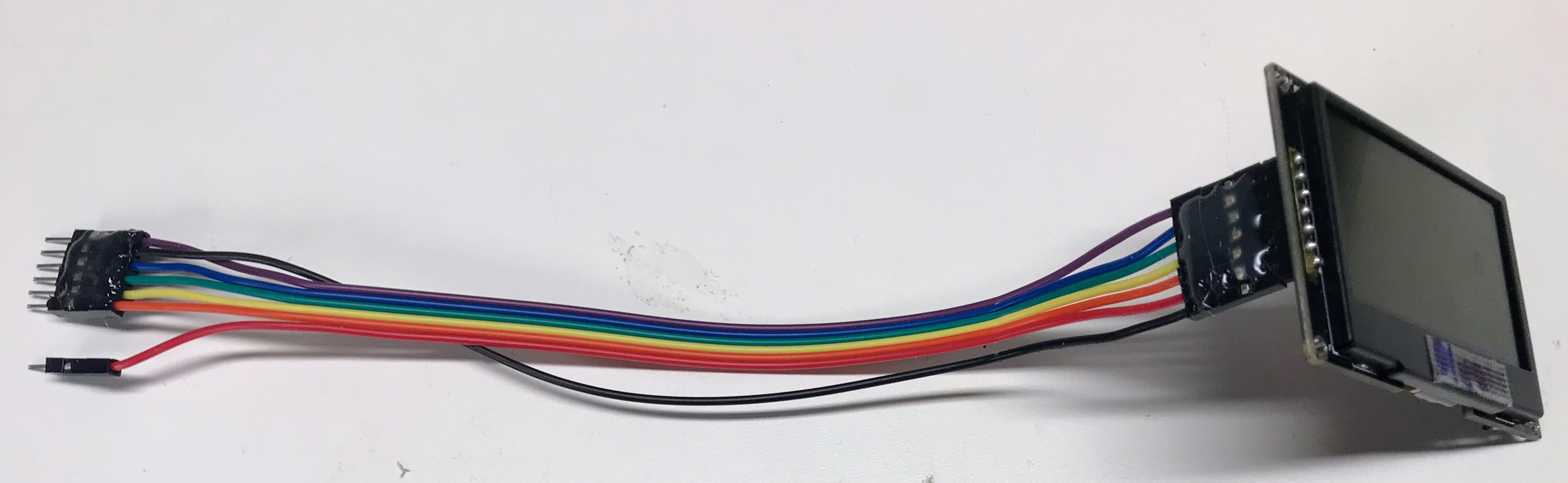
Here is the detailed wiring diagram showing how the wires go from the back of the OLED display to the pins on the breadboard:
Sample Python Code
This code names each pin with a clear constant. This makes it easy to change pin numbers later.
1 2 3 4 5 6 7 8 9 10 11 12 13 14 15 16 17 18 19 20 | |
What each line does:
1–5. Constants — store the GPIO pin numbers as easy-to-read names. Change these if your wiring is different.
6–10. Pin objects — create a Pin object for each wire so the driver can control them.
11. spi = machine.SPI(0, ...) — creates the Serial Peripheral Interface (SPI) bus using the clock and data pins.
12. oled = ssd1306.SSD1306_SPI(...) — creates the display object. WIDTH and HEIGHT are the pixel dimensions of your display (usually 128 and 64).
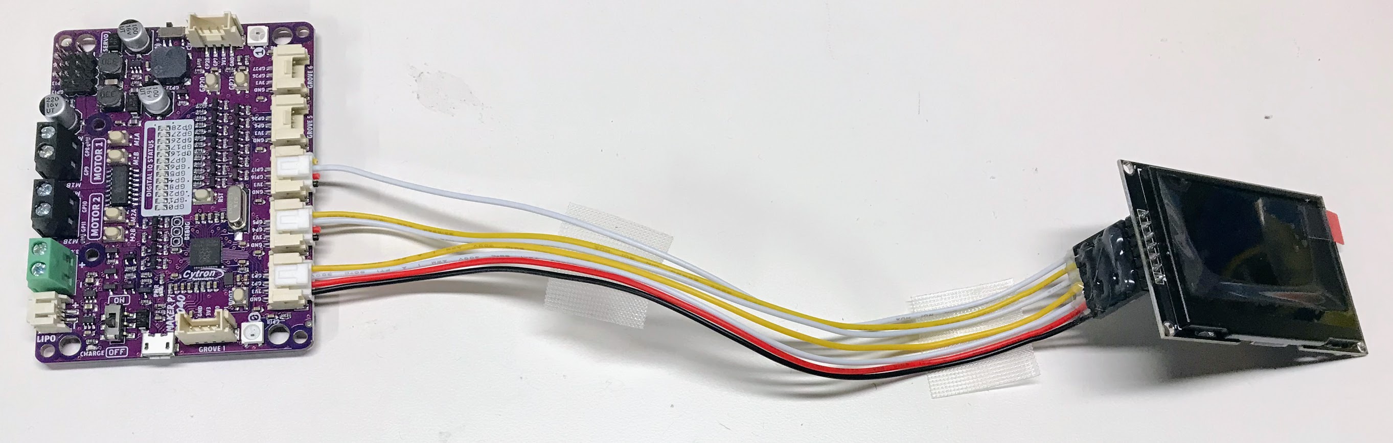
Building A Harness for the Cytron Maker Pi RP2040 Board
You can also make a display harness for the Cytron Maker Pi RP2040 Board. To do this you will need to use three Grove connectors. You use all four wires of the first Grove connector, two of the data wires on the second, and just one wire on the third Grove connector. This connector is shown below.
The MicroPython code for this harness is the following:
1 2 3 4 5 6 7 8 9 10 11 12 13 14 15 16 17 18 | |
Note
This code is exactly the same as the Pico version above with the exception of the CS_PIN which was on GPIO 6 but we now moved it to GPIO 16.
Great Work!
 You built a display wiring harness! Now your display will stay connected reliably every time you plug it in. Engineers use harnesses in real products for exactly this reason — nice work!