MicroPython ST7789V LCD Display
Welcome to the ST7789V Color LCD Lab
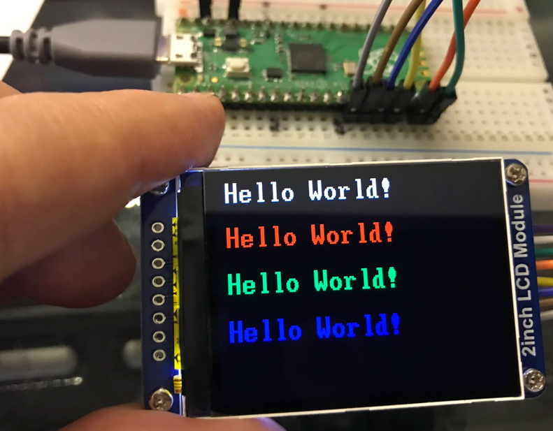
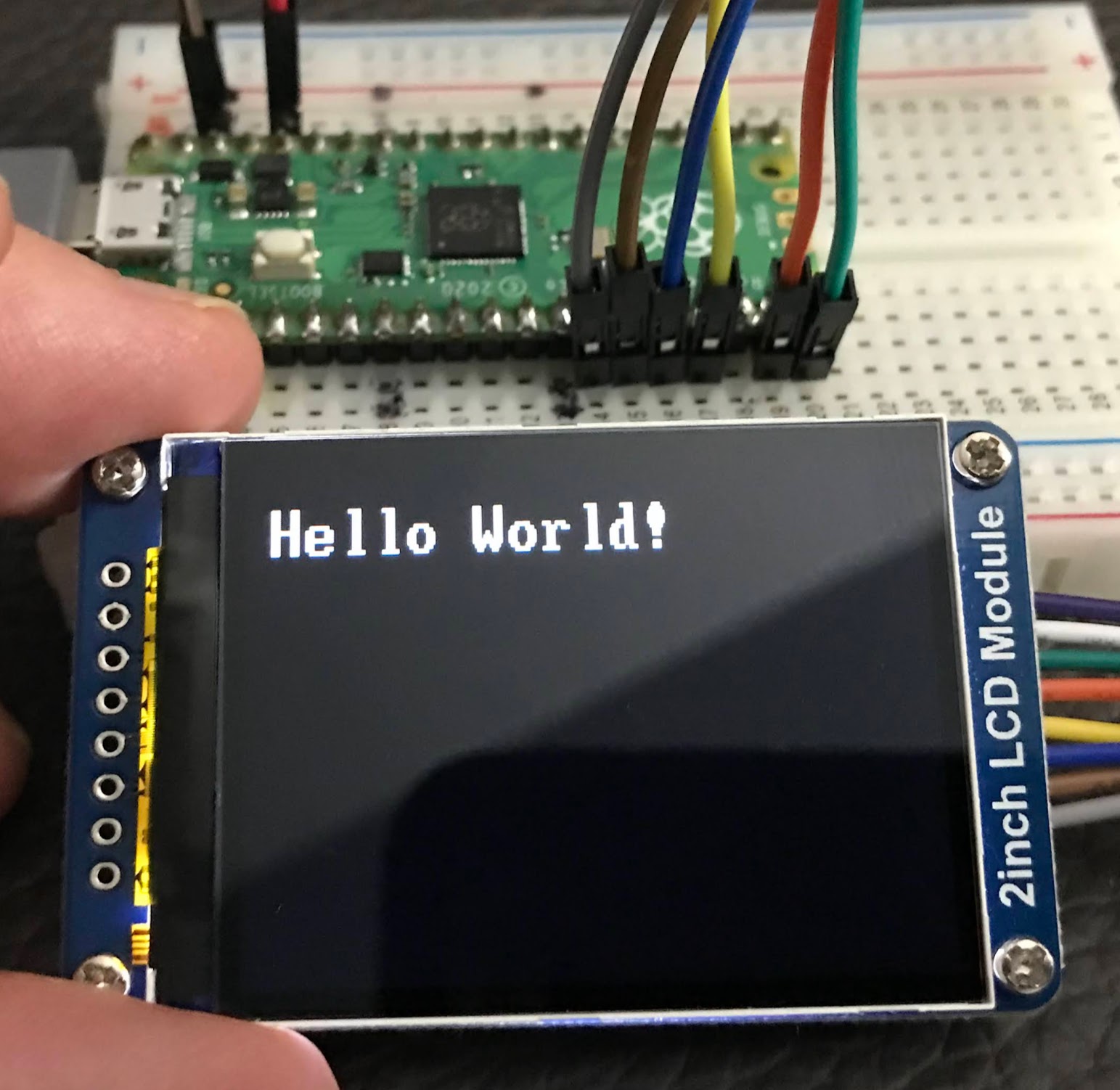
 In this lab, you will connect a beautiful 2-inch color display to your Pico and write code to show text in many colors. Let's paint the screen!
What Is This Display?
The ST7789 is a driver chip made by a company called Sitronix. It controls small color Liquid Crystal Displays (LCDs) that use an In-Plane Switching (IPS) panel. IPS panels look great from any angle — the colors stay bright even when you look at the screen from the side.
This lab uses a 2-inch color LCD made by Waveshare. It costs about $13 to $15.
Specifications
- Resolution: 240 pixels wide by 320 pixels tall
- Color depth: 18-bit color (6 bits each for Red, Green, and Blue)
- Interface: 4-wire Serial Peripheral Interface (SPI)
- Operating voltage: 3.3V
Important note about SPI: The ST7789 uses SPI to send data, but it only uses the MOSI (data out) wire. It does not send data back to the Pico. You only need four wires to connect it.
Device Interface
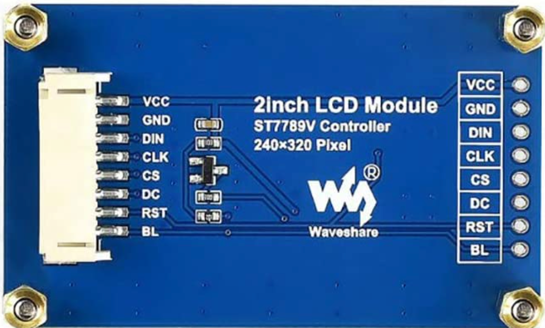
Here are the pins on the back of the display board:
- VCC — Power supply (connect to 3.3V)
- GND — Ground
- DIN — SPI data input (MOSI)
- CLK — SPI clock input
- CS — Chip select (active when set Low)
- DC — Data or Command select (High = data, Low = command)
- RST — Reset (active when set Low)
- BL — Backlight (tie to GND to turn the backlight on)
Although there are eight wires, the Pico only controls a few of them through General-Purpose Input/Output (GPIO) pins.
Watch Out!
 This display runs on 3.3V. Never connect it to a 5V power supply. Using 5V can damage the driver chip permanently.
Uploading the ST7789V Firmware
This display needs a special firmware file. The firmware includes the display driver and built-in fonts. You need to load it onto your Pico before running any code.
Follow these steps to install the firmware:
- Download the firmware file from this GitHub page. Look for a file ending in
.uf2. - Hold down the BOOTSEL button on your Pico.
- While holding BOOTSEL, plug the Pico into your computer with a USB cable.
- Release the BOOTSEL button. A new drive called RPI-RP2 will appear on your computer.
- Drag the
.uf2firmware file into that drive. - The Pico will restart automatically with the new firmware ready to use.
Wiring the Display to the Pico
Connect the display to Pico SPI port 1 using the pins along the lower-left corner of the Pico:
| Pico Pin Number | GPIO Number | Display Label |
|---|---|---|
| 14 | GP10 | BL (Backlight) |
| 15 | GP11 | RST (Reset) |
| 16 | GP12 | DC (Data/Command) |
| 17 | GP13 | CS (Chip Select) |
| 18 | GND | GND |
| 19 | GP14 | CLK (Clock) |
| 20 | GP15 | DIN (Data In) |
Why These Pins?
 The Pico has two SPI ports: SPI0 and SPI1. This wiring uses SPI1. The clock and data pins for SPI1 are fixed — they must be on GP14 and GP15. The other pins (CS, DC, RST, BL) can be on almost any GPIO.
Set Up the Display
1 2 3 4 5 6 7 8 9 10 11 12 13 14 15 16 17 18 19 20 21 22 23 24 25 26 27 28 | |
What Each Line Does
from machine import Pin, SPI— loads the tools for GPIO pins and SPI communication.import st7789— loads the display driver for the ST7789 chip.BACKLIGHT_PIN = 10throughDIN_PIN = 15— gives each wire a clear name instead of just a number.import vga1_bold_16x32 as font— loads a bold font where each letter is 16 pixels wide and 32 pixels tall.spi = SPI(1, baudrate=31250000, ...)— starts SPI port 1 at a very high speed.tft = st7789.ST7789(...)— creates the display object with all the pin settings.rotation=3— sets the screen to landscape mode with the origin at the top-left corner.tft.init()— sends startup commands to the display driver chip to wake it up.tft.text(font, "Hello World!", 10, 20, ...)— draws text. Thecolor565()function converts red, green, blue values into the 16-bit color format the display uses.
Show Text in Four Colors
1 2 3 4 5 6 7 8 9 10 11 12 13 14 15 16 17 18 19 20 21 22 23 24 25 26 | |
What Each Line Does
- Lines 1–16 are the same setup as before.
- Each
tft.text()call draws the same words at a different vertical position (0, 50, 100, 150 pixels from the top). color565(255,255,255)= white (all red, all green, all blue turned on fully).color565(255,0,0)= red (only red turned on).color565(0,255,0)= green (only green turned on).color565(0,0,255)= blue (only blue turned on).- The second
color565(0,0,0)in each line sets the background color to black.
Monty's Tip
 The
The color565() function takes three numbers — red, green, and blue — each from 0 to 255. Mix them to make any color you want!
How the Driver Handles Color
The ST7789V chip supports three different color formats. This display uses RGB565. In RGB565, each pixel is stored using 16 bits:
- 5 bits for red (0–31)
- 6 bits for green (0–63)
- 5 bits for blue (0–31)
This is why you use color565() — it converts normal 0–255 color values into the 16-bit format the display expects.
The SPI Communication Timing
The display uses 4-wire SPI. Here is what each wire does during communication:
- RESX (Reset): Must be set Low at power-on, then set High for normal operation.
- CSX (Chip Select): The display only listens when CS is set Low.
- D/CX (Data/Command): When Low, the Pico is sending a command. When High, the Pico is sending pixel data.
- SDA (Data): Carries the actual pixel data (RGB values).
- SCL (Clock): Keeps the data transfer in sync between the Pico and the display.
Timing Diagram
You can see how the data and clock signals work together in this diagram:
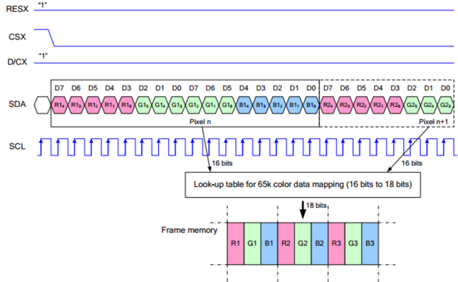
The SPI protocol uses two settings called clock polarity (CPOL) and clock phase (CPHA). Together they make four possible modes. This display uses SPI mode 0 (CPOL=0, CPHA=0). Data is sent 8 bits at a time, starting with the most significant bit.
References
Great Work!
 You connected a color LCD and showed text in four different colors! Next, try drawing shapes or displaying sensor readings on your screen.