Using a Transistor to Control a Motor
Welcome to the Transistor Lab
 In this lab, you will use a tiny electronic switch called a transistor to control a motor. The Pico sends a small signal, and the transistor does the heavy lifting!
Power Requirements for Motors
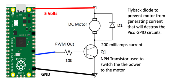
A DC hobby motor needs about 200 milliamps (mA) of current to spin. That is a unit of electrical flow — like water flowing through a pipe. The problem is that the Raspberry Pi Pico's output pins can only safely switch about 17 milliamps.
That is not enough to run a motor directly. If you connected a motor straight to a Pico pin, you could damage the Pico permanently.
The solution is to use a transistor. A transistor is an electronic switch. A tiny signal from the Pico turns it on, and when it is on, it allows a much larger current to flow through it — enough to spin the motor.
Key Idea
 Think of a transistor like a faucet handle. A small turn of the handle (the Pico's signal) controls a large flow of water (the motor current).
Parts You Need
- Transistor: NPN 2N2222A — the electronic switch
- Diode: 1N4148 — protects the transistor from voltage spikes
- Motor: 3–6 volt DC hobby motor
A diode is a component that lets current flow in only one direction. When a motor turns off, it can create a reverse voltage spike. The diode stops this spike from reaching and damaging the transistor. This is called a flyback diode.
Watch Out!
 Never connect a motor directly to a GPIO pin on the Pico. The motor draws too much current and can permanently damage the Pico's chip.
Wiring Steps
Connect the circuit in this order:
- Place the 2N2222A transistor on your breadboard.
- Connect the transistor's base pin to Pico GP21 through a 1 kΩ resistor.
- Connect the transistor's emitter pin to the breadboard's ground rail.
- Connect one motor wire to the transistor's collector pin.
- Connect the other motor wire to your external power supply positive (+).
- Place the 1N4148 diode across the motor terminals. The diode's stripe (cathode) goes toward the positive side.
- Connect your external power supply ground to the breadboard's ground rail.
- Connect the Pico's GND pin to the breadboard's ground rail.
PWM Control
You can control how fast the motor spins using Pulse-Width Modulation (PWM). PWM turns the transistor on and off many times per second. The longer it stays on during each cycle, the faster the motor spins.
PWM Frequency
Set the frequency to 50 Hz. That means 50 on-off cycles per second. One cycle takes 20 milliseconds (ms). The duty cycle is how long the signal stays HIGH during each cycle.
- A duty value of 51 (out of 1023) means the signal is HIGH for about 1 ms per cycle. This is slow speed.
- A duty value of 102 (out of 1023) means the signal is HIGH for about 2 ms per cycle. This is faster speed.
Sample Code
1 2 3 4 5 6 7 8 9 10 11 12 13 | |
What Each Line Does
| Line | What it does |
|---|---|
machine.Pin(21, machine.Pin.OUT) |
Sets GP21 as an output pin so it can send a signal |
machine.PWM(motor_pin) |
Creates a PWM object so we can control the speed |
motor_pwm.freq(50) |
Sets 50 Hz — the motor signal switches 50 times per second |
motor_pwm.duty(51) |
Sets the duty cycle to about 5% — a slow motor speed |
Try changing the duty value to 200, 500, or 900 to see the motor spin faster.
References
Nice Work!
 You used a transistor to control a motor with MicroPython! Next, you will learn how to make a motor spin in both directions using an H-bridge circuit.