MAX7219 8x8 LED Matrix
Welcome to the 8×8 LED Matrix Lab
 An 8×8 LED matrix is a grid of 64 tiny lights. You can draw letters, shapes, and animations — all with just 4 wires! Let's build something amazing!
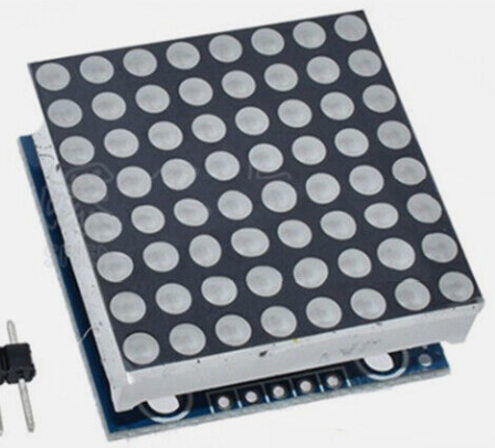
What Is an 8×8 LED Matrix?
An 8×8 LED matrix is a grid of 64 Light-Emitting Diodes (LEDs) arranged in 8 rows and 8 columns. A single driver chip called the MAX7219 controls all 64 LEDs. This keeps the wiring simple — you only need 4 wires between the Pico and the display.
This low-cost ($3) device is perfect for small projects that do not need a full graphical screen. You will be surprised at how creative you can be with just 64 pixels!
eBay Search for "MAX7219 8x8 matrix"
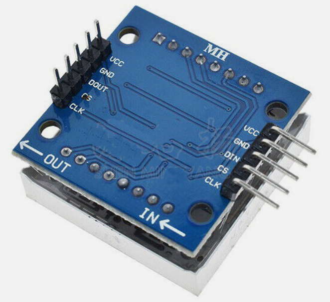
The device has five connectors:
- Power (VCC) — connects to 3.3 V or 5 V
- Ground (GND) — connects to GND
- Clock (SCK) — the timing signal for Serial Peripheral Interface (SPI) communication
- Data (MOSI — Master Out Slave In) — carries the data signal
- Chip Select (CS) — tells the chip when to listen
You communicate with the device using SPI. SPI is a way for two chips to share data using 3 or 4 wires. The Pico sends data, and the MAX7219 receives it and lights up the right LEDs.
There is also an easy-to-use driver library by Mike Causer. Download this file and copy it to your Pico before running the examples below.
Wiring Steps
- Connect VCC on the matrix to 3.3 V on the Pico.
- Connect GND on the matrix to any GND pin on the Pico.
- Connect SCK on the matrix to GP2 on the Pico.
- Connect MOSI (data) on the matrix to GP3 on the Pico.
- Connect CS on the matrix to GP4 on the Pico.
Quick Start: Show a Letter
Here is how you set up the driver and display one letter:
1 2 3 4 5 6 7 8 9 10 11 12 13 14 15 16 17 18 19 20 | |
What Each Line Does
| Line | Purpose |
|---|---|
SPI(0, baudrate=10000000, ...) |
Sets up the SPI bus at 10 MHz on bus 0 |
Pin(CS_PIN, Pin.OUT) |
Sets the Chip Select pin as an output |
max7219.Matrix8x8(spi0, cs, 1) |
Creates a matrix object for 1 display |
matrix.text('A', 0, 0, 1) |
Draws the letter A at column 0, row 0 |
matrix.show() |
Sends all the pixel data to the display |
Using Multiple Displays
You can chain up to 4 displays side by side. Change the last number in Matrix8x8() to match how many displays you have:
1 2 3 4 5 6 7 8 9 10 11 12 | |
Key Idea
 When you chain displays, data flows from one display to the next like a relay race. The Pico sends data to display 1, which passes extra data to display 2, and so on. That is why 4 displays still only need 4 wires!
Basic Program
1 2 3 4 5 6 7 8 9 10 11 12 13 14 15 16 17 18 19 20 | |
Full Demo
This program cycles through several different displays to show what the matrix can do:
1 2 3 4 5 6 7 8 9 10 11 12 13 14 15 16 17 18 19 20 21 22 23 24 25 26 27 28 29 30 31 32 33 34 35 36 37 38 39 40 41 42 43 44 45 46 47 48 49 50 51 52 53 54 | |
What Each Line Does
| Line | Purpose |
|---|---|
matrix.fill(0) |
Turns off all 64 pixels |
matrix.line(0, 0, 7, 7, 1) |
Draws a line from (col 0, row 0) to (col 7, row 7) |
matrix.rect(0, 0, 8, 8, 1) |
Draws a rectangle border starting at (0,0) that is 8 wide and 8 tall |
matrix.pixel(x, y, 1) |
Turns on one pixel at column x, row y |
matrix.show() |
Sends all pixel changes to the display |
Monty's Tip
 Try changing the numbers in
 matrix.pixel() to create your own face or design. The columns go from 0 (left) to 7 (right). The rows go from 0 (top) to 7 (bottom).
Great Work!
 You drew letters, lines, rectangles, and a smile face on an 8×8 LED matrix! Next, try the 4-Digit LED Display lab to build a working clock.