Sample Seven Segment Display Lab
Welcome to the Seven-Segment Display Lab
 A seven-segment display shows digits using seven glowing bars. You will learn how to control each bar with code and build a clock that shows minutes and seconds! Let's build something amazing!
4-Digit Seven Segment Display
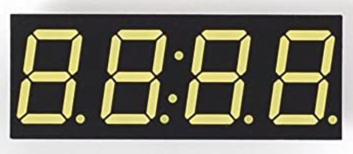
A seven-segment display shows a single digit (0–9) using seven Light-Emitting Diode (LED) segments. The segments are named a through g. Different combinations of segments light up to form each number. For example, turning on all seven segments shows the digit 8. Turning on just two vertical segments on the right side shows the digit 1.
A 4-digit seven-segment display puts four of these digits side by side. It can also have a colon (:) between the middle two digits — great for showing hours and minutes.
Always put a current-limiting resistor in series with each LED segment. A 330 Ω resistor is safe for 5 V circuits. A 220 Ω resistor works for 3.3 V circuits.
This code was provided by Jaison Miller from his GitHub Repo.
Key Idea
 Each segment is just an LED. A bitmap is a number where each bit controls one segment. The number
 0b00111111 has six bits set to 1 — that turns on segments a, b, c, d, e, and f, which together show the digit 0.
Wiring Steps
- Connect each segment pin (a–g) of the display to the matching GPIO pin listed in the
pin_segmentsdictionary in the code below. - Place a 220 Ω resistor in series with each segment pin.
- Connect each digit select pin (1–4) to the matching GPIO pin listed in
pin_digits. - Connect the colon pin to GP6 and the dash pin to GP8.
- Connect the decimal point pin to GP22.
- Connect the colon control pin to GP27 and the dash control pin to GP7.
- Connect all GND pins on the display to a GND pin on the Pico.
- Connect all VCC pins on the display to the 3.3 V pin on the Pico.
Watch Out!
 Do not skip the current-limiting resistors! Connecting LED segments directly to GPIO pins without resistors will burn out the LEDs and may damage your Pico.
Full Program
1 2 3 4 5 6 7 8 9 10 11 12 13 14 15 16 17 18 19 20 21 22 23 24 25 26 27 28 29 30 31 32 33 34 35 36 37 38 39 40 41 42 43 44 45 46 47 48 49 50 51 52 53 54 55 56 57 58 59 60 61 62 63 64 65 66 67 68 69 70 71 72 73 74 75 76 77 78 79 80 81 82 83 84 85 86 87 88 89 90 91 92 93 94 95 96 97 98 99 100 101 102 103 104 105 106 107 108 109 110 111 112 113 114 115 116 117 118 119 120 121 122 123 124 125 126 127 128 129 130 131 132 133 134 135 136 137 138 139 140 141 142 143 144 145 146 147 148 149 150 151 | |
What Each Line Does
| Line | Purpose |
|---|---|
number_bitmaps |
Dictionary that maps each digit (0–9) to a 7-bit pattern |
segment_masks |
Dictionary that maps each segment letter to a single bit |
segment_maps[segment].value(0) |
Turns a segment on (active LOW — 0 = on) |
segment_maps[segment].value(1) |
Turns a segment off |
display_number_bitmap & mask == mask |
Checks if this segment's bit is set in the bitmap |
lt_minute // 10 |
Integer division — gives the tens digit of the minute |
lt_minute % 10 |
Modulo — gives the units digit of the minute |
lt_second % 2 == 0 |
True on even seconds, false on odd seconds — makes the colon flash |
Monty's Tip
 The display uses multiplexing — it shows only one digit at a time, but switches between digits so fast that your eyes see all four at once. The two
 utime.sleep(0.001) calls control how long each digit is shown.
Great Work!
 You can now control every segment of a 4-digit display using bitmaps and dictionaries. That is some serious maker skill! Next, try the 4-Digit LED Display lab using the TM1637 library for an easier approach.