Character LCD Display
Welcome to the Character LCD Lab
 A character LCD screen can show 32 letters and numbers at once — 16 on each row! You will print messages, move the cursor, and even control the backlight with code. Let's build something amazing!
What Is a Character LCD Display?
A character LCD (Liquid Crystal Display) is a screen that shows text. The most popular size is the 16×2 model. It has 16 columns and 2 rows, so it can show 32 characters at once.
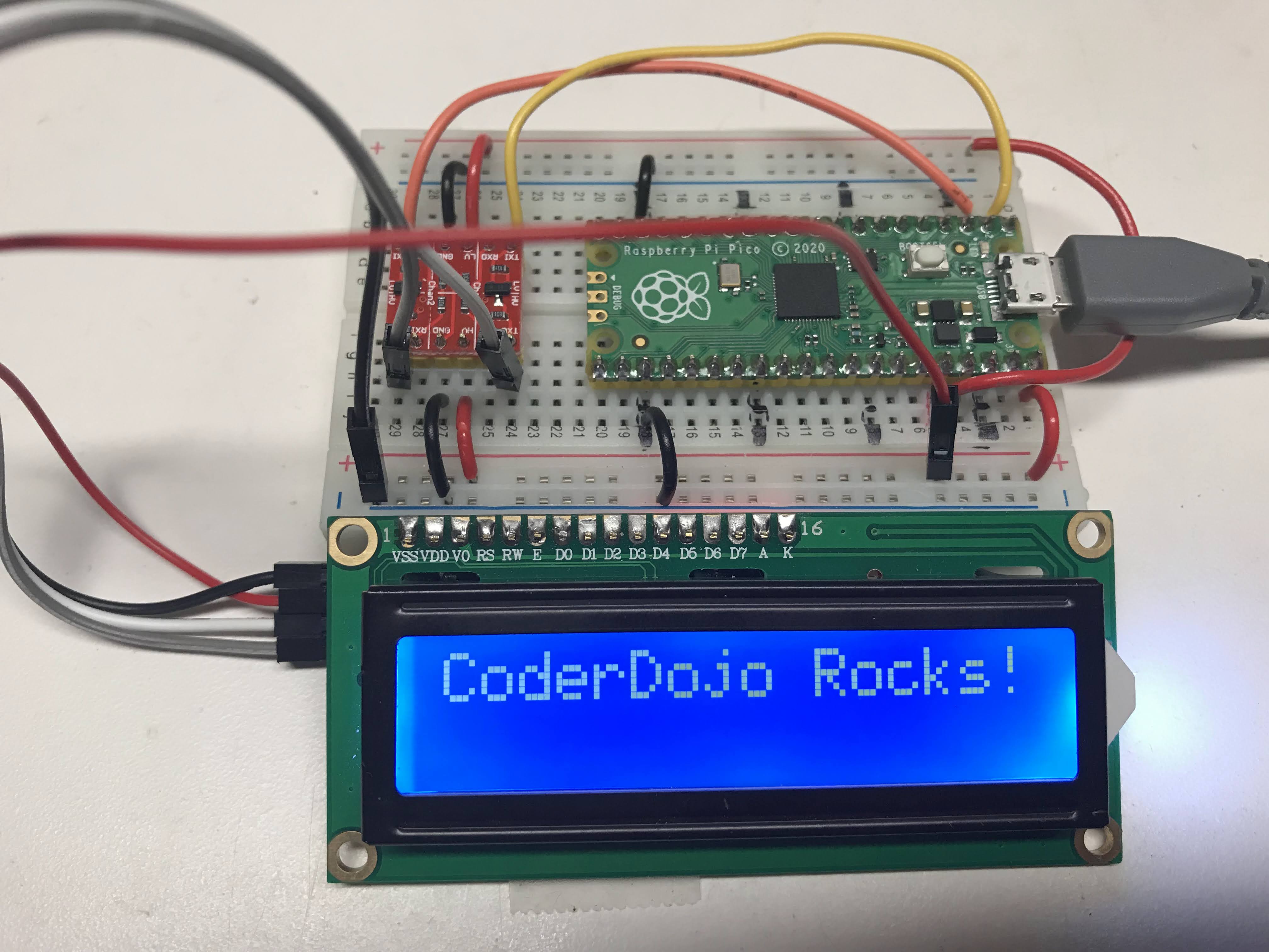
This lab uses the LCM1602 I2C LCD interface board. The I2C board clips onto the back of the LCD. It reduces the wiring from about 12 wires down to just 4.
Inter-Integrated Circuit (I2C) is a way for two devices to share data using just two signal wires. It is much simpler than connecting every pin separately.
The I2C board has four wires:
- GND — ground (negative power)
- VCC — power supply
- SDA — data wire (sends and receives data)
- SCL — clock wire (keeps the timing in sync)
The photo above shows a 3.3 V to 5 V voltage converter. Using 5 V gives the backlight more power and makes the screen easier to read. You can connect VCC to the Pico's 3.3 V pin, but the display may be harder to read in bright light.
Wiring Steps
- Connect GND on the I2C board to any GND pin on the Pico.
- Connect VCC on the I2C board to the 3.3 V pin on the Pico (or 5 V if you have a converter).
- Connect SDA on the I2C board to GP0 on the Pico.
- Connect SCL on the I2C board to GP1 on the Pico.
Watch Out!
 Make sure you connect SDA to GP0 and SCL to GP1. Swapping these two wires is a very common mistake. If the scanner finds no devices, check your SDA and SCL wires first.
I2C Address Scanner Test
Before you can use the LCD, you need to find its I2C address. Every I2C device has a unique address — a number the Pico uses to talk to it. Run this scanner code to find the address.
1 2 3 4 5 6 7 8 9 10 11 12 13 14 15 16 17 18 19 20 21 22 | |
What Each Line Does
| Line | Purpose |
|---|---|
machine.I2C(0, sda=..., scl=..., freq=400000) |
Sets up the I2C bus on bus 0 at 400 kHz |
i2c.scan() |
Scans all possible addresses and returns the ones that answer |
len(devices) |
Counts the items in the devices list |
hex(device) |
Converts the address to a hex number (like 0x27) |
Scanner Result
When the LCD is connected correctly, you should see output like this:
1 2 3 | |
Write down the hex address. You will need it in the next step. Most LCM1602 boards use address 0x27.
Key Idea
 The I2C address is like a house number on a street. The Pico sends a message to that address, and only the device at that address answers. If the scanner shows no devices, the wiring has a problem — check your connections.
Testing the LCD
Now you will display a message on the screen. This code uses two library files: lcd_api.py and pico_i2c_lcd.py. Copy both files to your Pico before running this.
1 2 3 4 5 6 7 8 9 10 11 12 13 14 15 | |
What Each Line Does
| Line | Purpose |
|---|---|
I2C_ADDR = 0x27 |
Stores the screen's I2C address |
I2cLcd(i2c, I2C_ADDR, I2C_NUM_ROWS, I2C_NUM_COLS) |
Creates the LCD object with the right address and size |
lcd.putstr("Hello, Maker!") |
Sends a string of text to the screen |
Putting the Device Through Display Option Tests
Once you can display text, you can explore all the other things the LCD can do. Here is a list of the most useful functions:
lcd.move_to(col, row)— move the cursor to a specific column and rowlcd.display_on()andlcd.display_off()— turn the display on or offlcd.show_cursor()andlcd.hide_cursor()— show or hide the blinking cursorlcd.blink_cursor_on()andlcd.blink_cursor_off()— make the cursor blink or stop blinkinglcd.backlight_on()andlcd.backlight_off()— turn the backlight on or offlcd.clear()— erase all text from the screen
The following test program cycles through all of these features automatically:
1 2 3 4 5 6 7 8 9 10 11 12 13 14 15 16 17 18 19 20 21 22 23 24 25 26 27 28 29 30 31 32 33 34 35 36 37 38 39 40 41 42 43 44 45 46 47 48 49 50 51 52 53 54 55 56 57 58 59 60 61 62 63 64 65 66 67 68 69 70 71 72 73 74 75 76 77 78 79 80 81 82 83 | |
What Each Line Does
| Line | Purpose |
|---|---|
utime.localtime() |
Returns the current date and time as a list |
lcd.putstr(...) |
Sends a formatted string to the LCD |
count % 10 |
Cycles through values 0–9 to test each feature in turn |
chr(x) |
Converts a number to its matching character (32 = space, 33 = !, etc.) |
count += 1 |
Adds 1 to count each loop |
Monty's Tip
 Use
Use lcd.move_to(col, row) to control exactly where your text appears. Row 0 is the top row and row 1 is the bottom row. Column 0 is the leftmost position.
References
Paul McWhorter Video on Using an LCD with an I2C Interface
ChatGPT response when asked how to use a 2-line LCD with MicroPython
MFitzp article on OLED displays
Great Work!
 You can now display text, move the cursor, and control the backlight on a 16×2 LCD! Next, try the NeoPixel Matrix lab to light up a full grid of color LEDs.